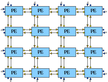
MESH2D, MESH3D, MESH4D, ... - Multi-dimensional arrays of entities.

Synopsis

This construct is similar to the 1-D Mesh Entities construct but with more than one dimension. For example, the MESH2D constructor is a special type of COMPENTITY which creates a 2-dimensional array of previously defined CHILD entities, e.g.

4-PE mesh

Syntax

MESHdimD name (
ENTITY_TYPE ( entity_type )
SIZE1( size1 ) SIZE2 ( size2 ) ...
NO_LINKS( 1 | 2 )
WRAP( 0 | 1 )
DESCRIPTION( "description" )
PARAMS( ref_parameters, ... )
)

Port names and links:

In order to select which port of an entity will be connected to which port of which neighbour entity, the following policy is applied:
The ith SOURCE port of an entity will be connected to the ith DESTINATION port of the closest following entity through the ith dimension.
When no_links=2, the (dim+i)th SOURCE port of an entity will be connected to the (dim+i)th DESTINATION port of the closest preceding entity through the ith dimension.

Example about links:

In the Mesh2D example below.
The 1st SOURCE port (to_right) is connected to the 1st DESTINATION port (from_left) of the closest following entity through the 1st dimension (x). As no_links = 2, the (dim+1 = 3)rd SOURCE port (to_left) is connected to the 3rd DESTINATION port (from_right) of the closest preceding entity through the 1st dimension.
The 2nd SOURCE port (to_bottom) is connected to the 2nd DESTINATION port (from_top) of the closest following entity through the 2nd dimension (y). As no_links = 2, the (dim+2 = 4)th SOURCE port (to_top) is connected to the 4th DESTINATION port (from_bottom) of the closest preceding entity through the 2nd dimension.
Thus PORTs should be declared as matching pairs in cyclic SOURCE order, i.e. right, bottom, left, top.

Screen Layout

Some of the screen layout information is generated automatically. Thus the forwarding SOURCE ports in a 2-dimensional array are set to be graphically displayed on the right of the child entities in the X (horizontal) direction, or on the bottom in the Y (vertical) direction. The backward SOURCE ports (if no_links equals 2) are displayed on the left of the child entities in the X direction, or on the TOP in the Y direction (and vice-versa for DESTINATION ports).

When the wrap flag is set, the LINKCORNER information is also generated.

Some optional information may also be added after the position information in the project definition, a set of integers specifying the spacing between the CHILD entities in each of the dimensions.

Mesh2D Example

The 4x4 processing element mesh shown above was produced using the following definitions:
ENTITYLIB (
ENTITY PE2 (
DESCRIPTION ("Procesing Element")
STATES (PE2_NORMAL)
PARAMS ()
PORTS (
PORT ( to_right, l_int, SOURCE)
PORT ( to_bottom, l_int, SOURCE)
PORT ( to_left, l_int, SOURCE)
PORT ( to_top, l_int, SOURCE)
PORT ( from_left, l_int, DESTINATION)
PORT ( from_top, l_int, DESTINATION)
PORT ( from_right, l_int, DESTINATION)
PORT ( from_bottom, l_int, DESTINATION)
)
);
MESH2D simd2 (
ENTITY_TYPE (PE2)
SIZE1 (4)
SIZE2 (4)
NO_LINKS(2)
WRAP(1)
DESCRIPTION("2-dimensional array")
PARAMS()
)
)
STRUCTURE (
AENTITY AENTITY simd2 SIMD2 (DESCRIPTION("2D SIMD")
)

Screen Layout

SIMD2 : position (20,30) 90 70

Entity Names

Entities generated in this example are named:

_0_0_   _1_0_   _2_0_   _3_0_
_0_1_   _1_1_   _2_1_   _3_1_
_0_2_   _1_2_   _2_2_   _3_2_
_0_3_   _1_3_   _2_3_   _3_3_

The first number is the coordinate in the first dimension, the second is the the coordinate is the second dimension (etc. for more dimensions)