Computer Architecture Simulation & Visualisation
Return to Computer Architecture Simulation Models

Snoopy Cache Coherence
In a bus-based multiprocessor system, cache coherence can be ensured
using a snoopy protocol in which each processor's cache monitors the
traffic on the bus and takes appropriate action when it sees a write
request being sent to memory for a variable at an address matching one
that it holds. This website contains a number of models demonstrating
different types of snoopy protocol.
- Write-Through / Write-Invalidate / No-Write-Allocate (WTWI-N) protocol,
for which the model files can be downloaded from snoop_v4.1.zip
- Write-Through / Write-Invalidate / Write-Allocate (WTWI-A) protocol,
for which the model files can be downloaded from snoop_v5.1.zip
- Write Through / Write Update (WTWU) protocol,
for which the model files can be downloaded from snoop_v6.1.zip
- Copyback / Write Invalidate (CBWI) protocol,
for which the model files can be downloaded from snoop_v7.1.zip
Instructions on how to use HASE models can be found at
Downloading, Installing and Using HASE.
Snoopy Cache Protocols
In any system with a cache, a read access to the cache generates a
Read Hit or a Read Miss. For a Read Hit, the cache simply returns the
requested value to the processor, while for a Read Miss the cache
control hardware sends a request to the next level in the memory
hierarchy (e.g. the Main Memory or a Level 2 Cache) and when it
receives a reply, updates whichever cache line has been selected to
hold the missing data. The way this line is selected depends on the
way the cache is organised, e.g. associative, set-associative
or direct-mapped.
Regardless of the organisation, the content of the selected line may
or may not have to be written back to the next level in the hierarchy,
depending on (a) whether the content is valid, i.e.
whether or not it contains an up-to-date copy of the data required in
the next hierarchy level; (b) on how the cache handles write
requests. If a write-through protocol is used, the cache line
can simply be overwritten; if a copyback protocol is used, the
existing content of a valid line must be written back to the next
level before it can be over-written. In the case of
a write-though protocol, it is not necessary to allocate a
cache line in the event of a Write Miss, so the protocol may or may
not do this. To implement a write-allocate protocol, each cache
line must have a modified bit (sometimes called a dirty
bit) as well as a valid bit. Clearly a copyback protocol
must also be a write-allocate protocol.
In a multi-processor system, some means must be provided to ensure
consistency between caches, since two or more caches may each contain
a copy of a particular variable. In bus-based systems, snoopy
protocols are normally used, whereby all the caches snoop on the bus
and can react to traffic generated by any of the other caches. There
is then a further protocol choice: whether to update
or invalidate any copies of a variable held in caches other
than the one executing a write request to that line.
HASE Snoopy Cache Models
The five HASE Snoopy Cache Protocol Models included here (three
earlier models are deprecated) all have the same structure in terms of
their entities and differ only in terms of the way the entities
interact and the number of status bits in each cache line. The caches
are all single-level, direct-mapped caches. As an example, Figure 1
shows the screen image of the Write-Through / Write-Invalidate /
No-Write Allocate Protocol model.
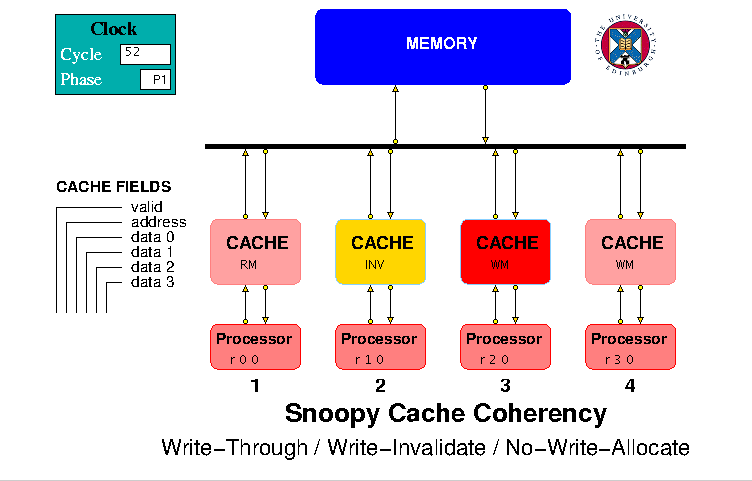
Figure 1. HASE Write-Through / Write-Invalidate / No-Write Allocate Protocol Model
In each model a memory and 4 caches are interconnected via a bus and
each cache is connected to a processor that generates a sequence of
read and write requests. The entities attached to the bus are numbered
0-5 with the memory being 0 and the caches 1-4. The memory simply
contains data values. The processors are modelled as arrays
containing sequences of read (r or R) and write (w or W) requests to
locations in the memory address space, e.g.
| r | 0 | 0 |
| r | 1 | 0 |
| w | 2 | 475 |
| r | 5 | 0 |
| w | 7 | 541 |
| z | 0 | 0 |
Both write and read requests require a data field, because of type
checking in the (C++ like) simulation language (Hase++) used to model
the entities. At the start of the simulation, each processor sends its
first request to its cache and, when it receives a response, issues
the next request in the succeeding clock period. When it encounters a
request which is not r, R, w or W, this is treated as an end-of-list
marker and the processor then increments a global
nodes_done variable. nodes_done is monitored by the bus
in each clock period and when it reaches 4, the bus stops the
simulation. If the user omits an end-of-list marker, the simulation
will eventually be stopped by a time-out.
The Caches
The caches each contain 8 lines, each of which contains three fields:
| Status | Address | Data |. In the Write-Through
models the status field is simply a valid bit, while in the
Copyback and Update models there are two bits: valid
and modified. The Data field (and each line in the memory) can
hold a quad-word (made up of 4 integer values), so within the cache the
2 least significant bits of an incoming address are used to select the
required data value within a quad-word. The remaining bits constitute
the quad-word address, the 3 least significant bits of which are used
to select a line in the cache. The Address field in a valid cache
line is the quad-word address of the data in the Data field, and when
a line is read from the cache, this address is compared with the
requested quad-word address to check for a Hit or a Miss.
The caches send and receive packets to/from their respective
processors and to/from the bus. The caches are all
initially idle and each becomes busy when it receives a
request from its processor. The actions that occur in response to a
processor request depend on whether it is a read or write request,
whether the request gets a hit or a miss in the cache and on the
protocol. In the case of a read hit, the cache simply sends the
required value back to the processor. In the case of a write hit, then
depending on the protocol, the cache may simply return an acknowledge
signal to the processor or may also send a packet to the bus destined
for the other caches and/or the memory. In the case of a read or write
miss, the cache always sends a packet to the bus, destined for the
other caches and/or the memory. Depending on the protocol, a cache may
also respond to an input from the Bus causing it to invalidate
(INV) or update (UPD) one of its lines.
The Bus
The bus has five pairs of inputs and outputs, one pair for each of the
caches and one for the memory. Access to the bus is controlled by a
request/grant mechanism, together with a round-robin priority
system. Each cache can make requests to take ownership of the bus but,
at any one time, only one request can be granted. Whilst a particular
cache has ownership of the bus, it can send packets to and receive
packets from the memory. Because the memory only sends packets in
response to cache requests, it does not need bus ownership.
A packet sent to the bus is forwarded to all units (caches and memory)
attached to the bus, apart from the sending unit. The memory only
responds to packets sent to it; a packet sent from the memory contains
the same source address as the packet it received. The caches act on
memory response packets containing their own source number and,
depending on the packet type and the protocol, on packets sent by
other caches. In a real computer system, all bus signals would be
active during any transfer but to avoid unnecessary screen clutter,
the models employ a number of different bus packet types, e.g.
READ_MEM, WRITE_MEM, READ_REPLY and WRITE_REPLY. A READ_MEM packet,
for example, does not include a data field.
None of the models contains a mechanism to ensure exclusive access to
data values. In a real multiprocessor system such a mechanism would
exist, to avoid two processors attempting to update the same variable
simultaneously and thus (at least potentially) leading to software
malfunctioning. In practice, in the models as in real hardware, only
one processor at a time can access the bus, so two processors can only
write to the same data location in succession though the order in which
they write is determined by the bus access protocol, so the outcome is
indeterminate from the processors' perspectives.
The Processors
The processor array files included in the model contain a series of
Read and Write requests which demonstrate the various protocol
actions. Users of the models are invited to observe the simulation
play-back to see their effects.
The processors are initially idle, become busy when
the simulation starts and each returns to the idle state
once it has sent its last request to its cache.
The Memory
The Memory can contain up to 4096 integer values held in an array of
1024 quad-words, i.e. each array element contains 4 integer
values. Only 32 of these quad-words are initialised by the
MEMORY.data_mem.mem file supplied as one of the model files, though
users can both extend this file up to the maximum defined size and
increase the array size by editing the .edl file. Table 1 shows the
data values held at each line of the memory, together with their
quad-word addresses and the cache line to which they are mapped
whenever they are in the cache.
Memory
Address | Data | Q-word
address | Cache
Line |
| 0 - 3 | 15 16 17 18 | 0 | 0 |
| 4 - 7 | 19 20 21 22 | 1 | 1 |
| 8 - 11 | 23 24 25 26 | 2 | 2 |
| 12 - 15 | 27 28 29 30 | 3 | 3 |
| 16 - 19 | 31 32 33 34 | 4 | 4 |
| 20 - 23 | 35 36 37 38 | 5 | 5 |
| 24 - 27 | 39 40 41 42 | 6 | 6 |
| 28 - 31 | 43 44 45 46 | 7 | 7 |
| 32 - 35 | 47 48 49 50 | 8 | 0 |
| 36 - 39 | 51 52 53 54 | 9 | 1 |
| 40 - 43 | 55 56 57 58 | 10 | 2 |
| 44 - 47 | 59 60 61 62 | 11 | 3 |
| 48 - 51 | 63 64 65 66 | 12 | 4 |
| 52 - 55 | 67 68 69 70 | 13 | 5 |
| 56 - 59 | 71 72 73 74 | 14 | 6 |
| 60 - 63 | 75 76 77 78 | 15 | 7 |
| |
Memory
Address | Data | Q-word
address | Cache
Line |
| 64 - 67 | 79 80 81 82 | 16 | 0 |
| 68 - 71 | 83 84 85 86 | 17 | 1 |
| 72 - 75 | 87 88 89 90 | 18 | 2 |
| 76 - 79 | 91 92 93 94 | 19 | 3 |
| 80 - 83 | 95 96 97 98 | 20 | 4 |
| 84 - 87 | 99 100 101 102 | 21 | 5 |
| 88 - 91 | 103 104 105 106 | 22 | 6 |
| 92 - 95 | 107 108 109 110 | 23 | 7 |
| 96 - 99 | 111 112 113 114 | 24 | 0 |
| 100 - 103 | 115 116 117 118 | 25 | 1 |
| 104 - 107 | 119 120 121 122 | 26 | 2 |
| 108 - 111 | 123 124 126 127 | 27 | 3 |
| 112 - 115 | 127 128 129 130 | 28 | 4 |
| 116 - 119 | 131 132 133 134 | 29 | 5 |
| 120 - 123 | 135 136 137 138 | 30 | 6 |
| 124 - 127 | 139 140 141 142 | 31 | 7 |
|
| Table 1. Address Mapping and Data in the Models |
Write-Through / Write-Invalidate / No-Write-Allocate Protocol
The simplest snoopy protocol is the write-through / write-invalidate
protocol with no-write-allocate. It requires each cache line to have a
single status bit to indicate whether or not the contents of the line
are valid, i.e. whether or not the line contains an
up-to-date copy of the corresponding line in the memory. The result of
a processor request can be Read Hit, Read Miss, Write Hit or Write
Miss; Tables 2 and 3 show the actions that occur for each. Table 4
shows the actions taken in response to a request sent to the bus by a
different cache for a memory line with a matching address.
| | Hit | Miss |
| Invalid | Cannot occur | Issue Read Miss
Next state: Valid |
| Valid | Supply data to processor
Next state: Valid | Issue Read Miss
Next state: Valid |
|
|
| | Hit | Miss |
| Invalid | Cannot occur | Write to memory
Next state: Invalid |
| Valid | Write to cache and memory
Next state: Valid | Write to memory
Next state: Valid |
|
| Table 2. CPU Initiated Actions: Read Requests |
|
Table 3. CPU Initiated Actions: Write Requests |
| | Memory Read | Memory Write |
| Invalid | No action | No action |
| Valid | No action | Invalidate
Next state: Invalid | |
|
| Table 4. Bus Initiated Actions |
Write-Through / Write-Invalidate / No-Write-Allocate Model
The HASE Write Through / Write Invalidate / No-Write-Allocate Protocol
(WTWI-N) model is shown Figure 1. The actions that occur in response
to a processor request depend on whether it is a read or write request
and whether the request gets a hit or a miss in the cache, i.e.
whether the (quad-word) address in the request matches the address in
the cache line accessed using the least significant 3 bits of the
quad-word address in the request and that the valid bit for that cache
line is set to 1. Except in the case of a read hit, the cache sends a
packet to the bus, destined for the memory. Bus packets contain some
or all of the fields shown in Table 5.
Packet
Type | MR | Memory Read Request |
| RR | Read Response from Memory |
| MW | Memory Write Request |
| WR | Write Response from Memory |
| Address | | |
| Data | | |
| Source | Number of the originating cache | |
|
| Table 5. WTWI-N Bus Packet Format |
Request Outcomes
The possible outcomes and actions for read requests and write requests are
shown in Tables 6 and 7.
| Outcome | State | Action |
| Read Hit | RH | Send data to processor |
| Read Miss | RM |
1. Issue Memory Read (MR)
2. When memory replies (RR),
write memory word to cache,
send data to processor |
|
|
| Outcome | State | Action |
| Write Hit | WH |
1. Send MW packet to memory
2. When memory replies (WR),
update cache and
send ack to processor |
| Write Miss | WM |
1. Send MW packet to memory
2. When memory replies (WR),
send ack to processor |
|
| Table 6. WTWI-N Read Request Outcomes |
|
Table 7. WTWI-N Write Request Outcomes |
For a Read Miss, the required line in the cache can simply be
overwritten with the new address and data because even if the line
already contains a valid entry, the data value in memory is guaranteed
to be the same as that in the cache: new values created by write
requests are always written to the memory. Because no line is
allocated in the cache in the case of a Write Miss, a choice has to be
made in the design as to whether the Memory should contain circuitry
to allow one word within a quad-word to be updated, or whether a
quad-word should be sent to the cache, updated and returned, but not
written into the cache. This model is based on the former choice, so
in the event of a Write Hit or a Write Miss, just the new value is
sent to the Memory, which updates the selected word within the
relevant quad-word. When the Memory acknowledges receipt by returning
a WR packet, the cache sends an acknowldege to the processor and in
the case of a Write Hit, updates its copy of the relevant
quad-word.
The caches act on WR packets containing their own source number and to
MW packets sent by other caches. If an MW packet sent by a different
cache contains the same address as a valid address in one of its own
lines, it sets the Valid bit for that line to 0. If the cache has an
outstanding read or write request when it invalidates a line
(i.e. it is waiting for a turn to access the bus), it re-checks
for a Hit or Miss.
Write-Through / Write-Invalidate / Write-Allocate Protocol
The Write-Allocate version of the Write-Through / Write-Invalidate
protocol differs from the No-Write-Allocate version in that, when a
Write Miss occurs, a request is made to memory for the missing
line. When this line is received in the cache, it is updated with the
value sent from the processor and then both written into the cache and
sent back to the memory. Tables 8 and 9 summarise the CPU initiated
actions for both read and write requests. Bus inititated actions are
identical to those shown in Table 4.
| | Hit | Miss |
| Invalid | Cannot occur | Issue Read Miss
Next state: Valid |
| Valid | Supply data to processor
Next state: Valid | Issue Read Miss
Next state: Valid |
|
|
| | Hit | Miss |
| Invalid | Cannot occur | Issue Write Miss
Next state: Valid |
| Valid | Write to cache and memory
Next state: Valid | Issue Write Miss
Next state: Valid |
|
| Table 8. CPU Initiated Actions: Read Requests |
|
Table 9. CPU Initiated Actions: Write Requests |
Write-Through / Write-Invalidate / Write-Allocate Model
The Write-Through / Write-Invalidate / Write-Allocate Model differs
from the Write-Through / Write-Invalidate / No-Write-Allocate Model
in terms of the actions that occur in the event of a Write Miss, as
shown in Tables 10 and 11.
| Outcome | State | Action |
| Read Hit | RH | Send data to processor |
| Read Miss | RM |
1. Issue Memory Read (MR)
2. When memory replies (RR),
write memory word to cache,
send data to processor |
|
|
| Outcome | State | Action |
| Write Hit | WH |
1. Send MW packet to memory
2. When memory replies (WR),
update cache,
send ack to processor |
| Write Miss | WM |
1. Issue Memory Read (MR)
2. When memory replies,
update word in quad-word
3 Send MW packet to memory
3. When memory replies (WR),
update cache,
send ack to processor |
|
| Table 10. WTWI-A Read Request Outcomes |
|
Table 11. WTWI-A Write Request Outcomes |
Write-Through / Write-Update Protocol
One of the first systems to implement a snoopy cache was the Sequent
Balance whicb used a Write-Through / Write-Invalidate protocol.
Because the valid bits were implemented in hardware external to the
cache memory circuits, they could be reset without involving a full
cache memory cycle. Otherwise, a cycle would have had to be "stolen"
from the processor, thus reducing performance.
The disadvantage of this scheme is that if a processor re-accesses a
variable shortly after that variable has been invalidated, it incurs a
considerable time penalty in making a relatively slow memory access to
retrieve the updated version. An alternative scheme is the
Write-Through / Write-Update protocol in which caches snoop on the bus
for memory write accesses and if they have a copy of the variable
being written to, update their own copy (a No-Write-Allocate version
of this protocol would of course be pointless.)
Write-Through / Write-Update Model
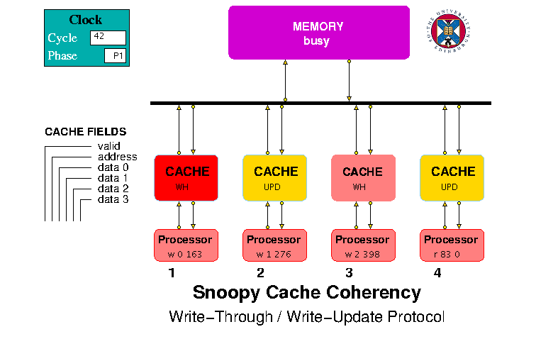
Figure 2. HASE Write-Through / Write-Update Protocol Model
The possible outcomes and actions for read requests and write requests
in the Write-Through / Write-Update Protocol Model (Figure 2) are
shown in Tables 12, 13 and 14. For both RM and WM, the required line
in the cache can simply be overwritten with the new address and data
because even if the line already contains a valid entry, the data
value in memory is guaranteed to be the same as that in the cache: new
values created by write requests are always written to the memory as
well as to the cache. When a Write Miss occurs, the required
quad-word has first to be read from memory, then updated and then
returned to memory and written into the cache. Whenever a Memory
Write is sent from any one cache to the bus, the other caches check
the address against their own valid lines and if there is a match,
update the contents of the matching line.
| Outcome | State | Action |
| Read Hit | RH | Send data to processor |
| Read Miss | RM |
1. Issue Memory Read (MR)
2. When memory replies (RR),
write data to cache and
send to processor |
|
| Outcome | State | Action |
| Write Hit | WH |
1. Send MW packet to memory
2. When memory replies (WR),
write memory word to cache,
3. Update cache,
4. Send ack to processor |
| Write Miss | WM |
1. Issue Memory Read (MR)
2. When memory replies, update value
3. Send MW packet to memory
4. When memory replies (WR),
write memory word to cache,
5. Update cache,
6. Send ack to processor |
|
| Table 12. WTWU Read Request Outcomes |
Table 13. WTWU Write Request Outcomes |
| | Memory Read | Memory Write |
| Invalid | No action | No action |
| Valid | No action | Update cache line
Next state: Valid |
|
| Table 14. WTWU Bus Initiated Actions |
Copyback / Write-Invalidate Protocol
The Copyback / Write-Invalidate (CBWI) protocol (see section 8.9 of
[1]) requires each cache line to have
two status bits: a valid bit and a modified bit. Each
line can be in one of three possible states, as shown in Table 15.
| State | Valid Bit | Modified Bit |
| Invalid | 0 | 0 |
| Valid | 1 | 0 |
| Modified | 0 | 1 |
|
|
Table 15. Cache Line States |
The actions that occur in the caches in response to read and write
requests from their respective CPUs and to signals from the Bus are
shown in Tables 16, 17 and 18. Figures 3 and 4 show the corresponding
state transition diagrams. The figures only show the state of a line,
so that when a Read Miss occurs whilst the line is in the Valid state,
for example, its content will change as a result of the Miss, but not
its state. On the other hand when a Write Hit ocurs whilst a line is
in the Valid state, its data is updated and its state changes to
Modified, but it still contains the same address.
| | Hit | Miss |
| Invalid | Cannot occur | Issue Read Miss
Next state: Valid |
| Valid | Supply data to processor
Next state: Valid | Issue Read Miss
Next state: Valid |
| Modified | Supply data to processor
Next state: Modified | Write to memory
Issue Read Miss
Next state: Valid |
|
|
| | Hit | Miss |
| Invalid | Cannot occur | Issue Write Miss
Next state: Modified |
| Valid | Issue Invalidation
Write data
Next state: Modified | Issue Write Miss;
Next state: Modified |
| Modified | Write data
Next state: Modified | Write to memory
Issue Write Miss
Next state: Modified |
|
| Table 16. CPU Initiated Actions: Read Requests |
|
Table 17. CPU Initiated Actions: Write Requests |
| | Read Miss | Write Miss | Invalidation |
| Invalid | No action | No action | No action |
| Valid | No action | Supply data
from memory
Next state: Valid | Next state:
Invalid |
| Modified | Supply data
Update memory
Next state: Valid | Supply data
Update memory
Next state: Invalid | n/a |
|
| Table 18. Bus Initiated Actions |
|
|
 |
| Figure 3: CPU Initiated State Transitions
|
| Figure 4: Bus Initiated State Transitions |
Copyback / Write Invalidate Model
The HASE Copyback / Write Invalidate protocol model is shown in Figure
5. This model differs from those described above by having two bits in
the cache line Status field, valid and modified. It
also uses an additional packet type, BR in Table 19, signifying
a Bus Read Request, sent to the bus when a cache gets a read or write
miss on a request from its processor. If the target line for the
request already contains a different, modified quad-word, this line is
sent to the memory (copyback). After this the actions are the same as
for a miss requiring an unmodified line. The first of these actions
involves sending a BR request: if one of the other caches has a
modified copy of the required quad-word when it receives a BR request,
it must copy that quad-word back to Memory in the next clock period,
using an MW packet, and mark its line Invalid. The originating cache
monitors the bus for the occurence of such an MW packet. If there is
no MW packet, it can immediately send an MR packet requesting the
missing quad-word; if there is an MW packet, it must wait for the WR
packet from the Memory to appear on the bus before sending its MR
packet. This mechanism ensures that, at any one time, only one cache
can ever hold a modified copy of a quad-word.
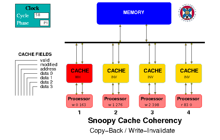
Figure 5. HASE Copyback / Write Invalidate Protocol Model
Packet
Type |
BR | Bus Read Request (to other caches) |
| IV | Invalidate |
| MR | Memory Read Request |
| MW | Memory Write Request |
| RR | Read Response from Memory |
| WR | Write Response from Memory |
| Address | | |
| Data | | |
| Source | Number of the originating cache | |
|
| Table 19. Bus Packet format |
More than one cache can of course hold a copy of an unmodified
quad-word, so if a write request from a processor gets a Write Hit on
an unmodified line, that cache must send an IV (Invalidate)
packet to all the other caches and set its own copy to Modified.
Tables 20 and 21 summarise all the actions that can occur in response
to processor read and write requests. Table 22 shows the actions that
occur in response to packets received from the Bus.
| Outcome | State | Action |
Read Hit
Unmodified | RH |
Supply data to processor;
state remains unchanged |
Read Hit
Modified | RH |
Supply data to processor;
state remains unchanged |
Read Miss
Umodified | RM |
1. Send Bus Read Request
2. In next clock cycle:
check if there's an MW packet
(a) if not, issue Memory Read
(b) if so, wait for WR packet
then issue Memory Read
3. When memory replies (RR),
write data to cache,
send data to processor |
Read Miss
Modified | RMM |
1. Write modified data to memory
2. Proceed as for
Read Miss Unmodified |
| |
| Outcome | State | Action |
Write Hit
Unmodified | WH |
1. Send Invalidate packet to Bus
2. Write data to cache
3. Set state to Modified |
Write Hit
Modified | WHM |
Write data to cache;
state remains unchanged |
Write Miss
Unmodified | WM |
1. Send Bus Read Request
2. In next clock cycle:
check if there's an MW packet
(a) if not, issue Memory Read
(b) if so, wait for WR packet
then issue Memory Read
3. When memory replies (RR),
write updated data to cache |
Write Miss
Modified | WMM |
1. Write modified data to memory
2. Proceed as for
Write Miss Unmodified |
|
| Table 20. Read Request Outcomes |
|
Table 21. Write Request Outcomes |
| BR | If state is Modified, send MW request to bus to write
value back to memory;
set state to Invalid, re-check for hit/miss |
| IV | Set state to Invalid |
| RR | If processing a Read Request, write quad-word to the cache line,
send required word to processor
If processing a Write Request, update quad-word with value from processor,
write quad-word to cache line |
| WR |
If processing Read Miss Modified, proceed as for Read Miss Unmodified
If processing Write Miss Modified, proceed as for Write Miss Unmodified
If a BR packet has been sent, proceed with Read Request
|
|
| Table 22. Bus Packet Actions |
Results
When downloaded, the models all contain the same set of read and write
requests in their processor array files, so at the end of the
simulations of the Write-Through models, their memories should all
contain the same values, even though the cache contents may be
different. For the Copyback model, the cache contents will also be
different from the others but so too would the Memory if the cache
contents were not purged back to Memory. To allow correct operation of
the Copyback model to be checked, the code for its Cache entity
includes extra instructions in the $report section that writes any
modified lines in the caches back to the Memory.
Table 23 shows the number of read accesses and write accesses made in
each model, the hit rates for each of the caches, the average hit rate
and the number of clock cycles required to complete the simulation.
These results are not particularly significant since the number of
requests made by the processors are very small. The simulations are
simply intended to demonstrate the actions that occur in the models as
the requests are processed.
| WTWI-N | WTWI-A | WTWU | CBWI |
| Memory Read Accesses | 18 | 25 | 21 | 25 |
| Memory Write Accesses | 10 | 10 | 11 | 6 |
| Cache 1 Hit Rate | 30% | 40% | 50% | 40% |
| Cache 2 Hit Rate | 40% | 50% | 50% | 50% |
| Cache 3 Hit Rate | 40% | 40% | 50% | 50% |
| Cache 4 Hit Rate | 30% | 30% | 40% | 30% |
| Average Hit Rate | 35% | 40% | 47.5% | 42.5% |
| Clock cycles | 147 | 182 | 162 | 206 |
|
| Table 23. Simulation Results |
Reference
-
M.J. Flynn
"Computer Architecture"
Jones and Bartlett, 1995. Return
Return to Computer Architecture Simulation Models
HASE Project
Institute for Computing Systems Architecture, School of Informatics,
University of Edinburgh
Last change 12/04/2023