Computer Architecture Simulation & Visualisation
Return to
Computer Architecture Simulation Models

MU5
MU5 was the fifth computer system to be designed and built at the
University of Manchester, in succession to a series of innovative
projects dating back to the late 1940s. MU5 introduced a number of new
ideas, particularly in terms of its instruction set, which was
designed with high-level language compilation in mind, and novel uses
for associative stores. The technical aspects of the project have been
well documented in numerous papers and a book. Many of the design
ideas developed in MU5 were used in the ICL 2900 series of computers.
This webpage describes the design of the MU5 computer, explains how
the HASE simulation model works and includes a list of relevant
publications. The most recent version of the model (V4.1) includes a
GLOBALS parameter Program that can be edited after the model has
been loaded into HASE. Program can take values of 1, 2 or 3,
allowing the user to select one of three programs contained in the
model. After editing, clicking the "Write Parameters" button
 updates the model's parameters file.
Program 1 demonstrates the operation of the MU5 Name Store,
Program 2 executes a scalar product program, Program 3 demonstrates
the use of string processing instructions.
updates the model's parameters file.
Program 1 demonstrates the operation of the MU5 Name Store,
Program 2 executes a scalar product program, Program 3 demonstrates
the use of string processing instructions.
The files for version 4 can be downloaded
from MU5_V4.1.zip.
Instructions on how to use HASE models can be found at
Downloading, Installing and Using HASE.
Overview
Figure 1 shows an image of the HASE user interface with the
simulation model of MU5 in the main (right hand) Project View pane and
model parameters (e.g. register and store contents) in the
(left hand) Project Inspector pane. The lower, Output pane shows
information produced by HASE. The icons in the top row allow the user
to load a model, compile it, run the simulation code thus created and
to load the trace file produced by running a simulation back into the
model for animation.
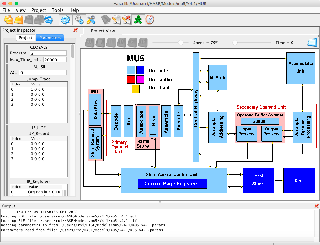
Figure 1. The MU5 simulation model loaded into HASE
Once a trace file has been loaded, the animation control icons at the
top of the Project View window become active (Figure 2). From left to
right, these allow the animation to be rewound, stopped, paused,
single stepped, run or fast forwarded to the end. As the animation
proceeds, packets of information can be seen passing between entities
while the entities themselves change colour to reflect their states
(idle, busy, waiting).
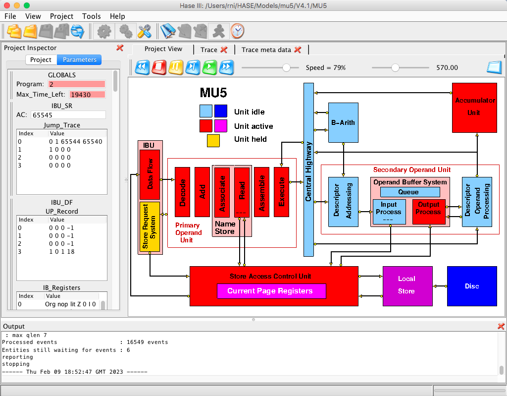
Figure 2. The MU5 simulation model during animation
The model contains 23 active units (entities in simulation terms).
These are the Console, the two parts of the Instruction Buffer Unit,
the six stages of the Primary Operand Unit (PROP), plus one for PROP
itself (containing the beat generation code), the Central Highway, the
B-Arithmetic Unit, the Descriptor Addressing and the Descriptor
Operand Processing Units, the three sections of the Operand Buffer
System, the Accumulator Unit, the Store Access Control Unit
(containing the Current Page Registers), the Local Store and the Disc
Store. Although they are shown on-screen as parts of the model, the
IBU, Name Store, SEOP and Operand Buffer System entities are simply
icons, with no corresponding simulation code. The 23rd entity is a
time counter containing a limit on the total number of simulation time
steps, to prevent run-aways; its icon is the key to the unit
states.
MU5 Design Considerations
During the design of MU5 the prime target was fast, efficient
processing of high-level language programs in an interactive
environment. This requirement led to the need for an instruction set
which satisfied the following conditions:
- Generation of efficient code by compilers must be easy.
- Programs must be compact.
- The instruction set must allow a pipeline organisation of the
processor leading to a fast execution rate.
- Information on the nature of operands should be available to
allow optimal buffering of operands.
Algol and FORTRAN were taken as being typical of two major classes of
programming languages in common use at the time, distinguished by the
use of recursive routines (or procedures) and dynamic storage
allocation in the former, and non-recursive routines and compile time
storage allocation in the latter, but having the following features in
common:
- Each routine has local working space consisting of named variables of
integer (fixed-point) and real (floating-point) types, and structured
data sets (arrays, for example) which are also named.
- A routine may refer to non-local names either of an enclosing routine
or in a workspace common to all routines.
- Statements involve an arbitrary number of operands which may be real
names, array elements, function calls or constants.
In order to reconcile feature 3 with condition 1 and 4, it was decided
that there would be an address form corresponding to each of the
different operand forms. However, it was felt that to have more than
one such operand specification per instructions would conflict with
conditions (2) and (3). The option of using addressable fast registers
to allow short instructions was also rejected. There were two
arguments against registers. The first was the desire to simplify the
software by eliminating the need for compilers to optimise their use.
The second was the desire to avoid the need to dump and restore
register values during procedure entry and exit and process changes.
The alternative arrangement proposed for MU5 was a small associatively
addressed Name Store, described in more detail below.
The MU5 instruction set
To avoid tortuous grammatical constructs, the following description
of MU5 is written in the present tense, even though the real MU5 no
longer exists.
The instruction format chosen for MU5 represents a merger
of single address and stacking machine concepts. All the arithmetic
and logical operations involve the use of an accumulator and an
operand specified in the instruction, but there is a variant of the
load order (*=) which causes the accumulator to be stacked before
being re-loaded. In addition, there is an address form (STACK) which
unstacks the last stacked quantity. Thus the expression
RESULT := (A + B) * ((C + D)/(E + F))
can be compiled into
| ACC = A |
| ACC + B |
| ACC *= C |
| ACC + D |
| ACC *= E |
| ACC + F |
| ACC ∅ STACK |
| ACC * STACK |
| ACC => RESULT |
The function ∅ is reverse divide
(i.e. ACC = STACK/ACC); if the operand to the left of
an operator is stacked, it subsequently appears as the right hand side
of a machine function (as the dividend in this case). Thus, for the
non-commutative operations - and /, the
corresponding reverse operations have to be provided. In pure stacking
machines, all subtractions and divisions are implicitly reverse
operations.
The instruction set is summarised in Figure 3. There are two basic
formats, one for computational functions and one for organisational
functions (control transfers, base register manipulations, etc.).
They are distinguished by the
type of function bits and use four and six bits respectively
to specify the function. The remaining nine or seven bits specify
the primary operand. The
k field indicates the kind of operand, and determines how
the n field is interpreted. Where the k field
indicates the Extended Operand Specification, the instruction is
extended by an additional 16 bits in the case of a name, or by 16, 32,
or 64 bits in the case of a literal.
Figure 3. The MU5 instruction set
The virtual address space is formally segmented: the unique identity
of store words belonging to different processes is maintained by
splitting the address into three separate fields, a 4-bit Process
Number, a 14-bit Segment Number, and a 16-bit address defining a
32-bit word within a segment. Segments 8192 to 16383 are common to all
processes, allowing a single copy of a compiler, for example, to be
shared by all active processes. Scalar variables are normally held in
a single segment of a process (normally segment 0) at addresses formed
by adding the 6 or 16-bit name in the instruction to the contents of
the Name Base register (RNB). The name segment number and the process
number (both held in special registers in the processor) are
concatenated with these addresses to form the full virtual addresses
required for store accessing. The value held in RNB is unique to the
name space associated with each procedure, and is altered at each
procedure change. Accesses to names of other procedures and to common
variables are made using the Extra Name Base (RXNB), while using zero
as base allows absolute addressing into the Name Segment (to access
the Name Base values of different procedures, for example). The Stack
Front register (RSF) points to the area immediately beyond the name
space of the current procedure, so that stacked variables are
contained within the same address space as the names. RSF is
automatically incremented or decremented during the execution of a
stacking function or a STACK operand access respectively.
Scalar variables can be of size 32 bits and 64 bits. They are accessed
from a 32-line Name Store using an address formed by adding the name
to the base register specified in the instruction (implicitly the Name
Base in 16-bit instructions). The Name Store has two parts, 32
associatively accessed address registers and 32 64-bit value
registers, so although a name + base address can point to a 32-bit
variable, the base registers themselves can only point to 64-bit
quantities. Thus the least significant bit of each of the base
registers is set to zero and the name of a 64-bit variable is shifted
left one place before being used to form an address.
Access to array elements is achieved through a descriptor mechanism.
When a data structure element is specified by the k field, the
corresponding primary operand is a 64-bit descriptor. This descriptor
is sent to a D-unit within the processor, together with the contents
of the B register if the k field specifies modification. The
D-unit interprets the descriptor and makes a secondary store
access for the element. This detachment of secondary addresses from
instructions, and the use of names within instructions, allows the
full 30-bit virtual address space available to a process to be
referenced by 16-bit instructions.
There are two main types of descriptor:
| String descriptor: | Ts | Length | Origin |
| Vector descriptor: | Tv | Bound | Origin |
| | 8 | 24 | 32 |
String descriptors describe strings of bytes. The length field
specifies the number of bytes, and the origin specifies the byte
address of the first byte. Strings are normally used in conjunction
with string processing orders (which may be two-address operations
involving the use of two descriptors). These orders provide
facilities for the manipulations of data records in languages such as
COBOL, PL/1 and Algol 68 (move, compare, logically combine, etc.).
The size of the elements in a vector is specified within the type bits
(Tv) and may be between 1 and 64 bits. If the operand access is
modified, the modifier must be greater than or equal to zero and less
than the bound. This check is carried out automatically by hardware
with virtually no time penalty, and removes the need for the costly
software bound check which is often required, particularly during
program development.
The Simulation Model
In any simulation modelling system there is a trade-off between
accuracy and performance. HASE was designed primarily as a high-level
visualisation tool for computer architecture students and therefore
simulates systems at register/word level rather than bit level. This
inevitably imposes some limitations on the way models can be
constructed, e.g. registers are modelled using typed variables and
stores are modelled as arrays of typed variables. Thus the HASE MU5
simulation model is intended to provide a visual demonstration of the
workings of the processor and memory system, rather than being
designed to run real MU5 programs. There are also constraints on
nomenclature. The type field, function field, etc in instructions are
modelled using the C++ enum construct, the elements of which can only
contain alphanumeric characters. Thus the MU5 function
'NB =', for example, is represented in the model as
'NBld' and the base registers are given the names used in the
hardware design diagrams (RNB, RXNB, RSF) to avoid clashes with NB,
XNB, SF in instructions.
The Instruction Set
The MU5 instruction set used in the model follows the spirit of the
original, rather than the detail, in particular because the instruction
format and size have to be fixed in HASE, rather than both being
variable as they were in MU5. In fact these restrictions are not
particularly significant: it was difficult for compilers to optimise
object code to use the short-form 16-bit format, so apart from the
long literals option (32-bit and 64-bit), most instructions were 32
bits long anyway. The instruction set of the ICL 2900 series, which
was closely modelled on that of MU5, did not allow the long literal
options and the MU5 hardware designers would themselves have gladly
forgone this option.
Figure 4 shows the instruction set used in the model..
The additional Type of Instruction (T) character is included in
instruction registers, and in packets containing instructions,
to represent the extra function bits that were used in the
hardware of MU5 to control the execution of instructions. Details
are given below in the Primary Operand Unit section.
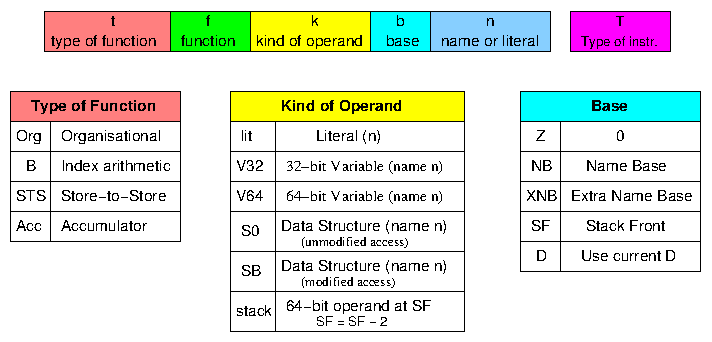
Figure 4. The HASE MU5 instruction set
The functions are shown in the table below. Empty boxes correspond to
functions that have not yet been implemented in the model (and in some
cases may never be), or did not exist in the real MU5. "Op" means
"operand"
The B functions correspond exactly to those implemented in MU5. COMP
(compare) sets the two test bits T1 (= 0 / ≠ 0)
and T2 (≥ 0 / < 0) according to the result of B -
operand; B itself remains unaltered. In the real MU5, a third
test bit (T0) was set to 1 if the comparison produced an overflow; in
the model, an arithmetic overflow would be caught by the underlying
runtime system, so T0 is not implemented. CINC
(compare & increment)
acts similarly but increments B after the comparison. CINC was
intended for use with a subsequent conditional branch instruction in
the implementation of for loops.
The ACC (Accumulator) functions are implemented in the model in
exactly the same way as the corresponding B functions, i.e. as
32-bit integer operations, rather than as floating-point
operations. The reason for this is explained below in the Address Space
section.
The STS functions (SLGC, SMVB, SCMP, BLGC, BMVB, BMVE, SMVF, BSCN and
BCMP) perform string processing operations. They were designed for use
in record processing applications written in languages such as COBOL,
PL/1 and Algol68. Their operation is explained in the description of
the actions that take place during execution of the String Processing
Program (Program 3) in the model,
| Organisational |
| Function | Action | Function | Action | Function | Action | Function | Action |
| BR | ->
(CO = CO + Op) | EXIT | | | | | |
| JUMP | CO = Op | RETURN | | | | | |
| XC0 | eXecutive Call
not implemented | XC1 | | XC2 | | XC3 | |
| XC4 | | XC5 | | XC6 | | STACK LINK | |
| MS = | | | | | | SET LINK | |
| XNB_LD | RXNB = Op | | | XNB_PL | RXNB = RXNB + Op | XNB_ST | RXNB => Op |
| SF_LD | RSF = Op | SF_PL | RSF = RSF + Op | SFNB_PL | RSF = RNB + Op | SF_ST | RSF => Op |
| NB_LD | RNB = Op | NBSF_PL | RNB = RSF + Op | NB_PL | RNB = RNB + Op | NB_ST | RNB => Op |
| BReq | -> if = 0 |
BRne | -> if /= 0 |
BRge | -> if >= 0 |
BRlt | -> if < 0 |
| BRle | -> if =< 0 |
BRgr | -> if > 0 |
OVERFLOW | -> if overflow
(not implemented) |
BRBn | -> if Bn = 1 |
| Bneq | Set Bn if = 0 |
Bnne | Set Bn if /= 0 |
Bnge | Set Bn if >= 0 |
Bnlt | Set Bn if < 0 |
| Bnle | Set Bn if =< 0 |
Bngr | Set Bn if > 0 |
OVERFLOW | Set Bn if overflow
(not implemented) |
BnBn | Set Bn if Bn = 1 |
| | | | | | | | |
| | | | | | | | |
| | | | | | | | |
| | | | | | | | |
| B | STS/D | ACC |
| Function | Action | Function | Action | Function | Action | Function | Action |
| LD | B = Op | XDO_LD | XDO = Op | DO_LD | DO = Op | LD | ACC = Op |
| LDD | B = Op - 1 | XD_LD | XD = Op | D_LD | D = Op | nop | |
| SLD | Stack B
B = Op | STACK | Stack Op | D_SLD | Stack D
D = Op | SLD | Stack ACC
ACC = Op |
| ST | B => Op | XD_ST | XD => Op | D_ST | D => Op | ST | ACC => Op |
| ADD | B = B + Op | XDB_LD | XDB = Op | DB_LD | DB = Op | ADD | ACC = ACC + Op |
| SUB | B = B - Op | | | | | SUB | ACC = ACC - Op |
| MUL | B = B * Op | | | MOD | DO = DO + Op
DB = DB - Op | MUL | ACC = ACC * Op |
| DIV | DUMMY | XMOD | XDO = XDO + Op
XDB = XDB - Op | | | DIV | ACC = ACC / Op |
| XOR | B = B xor Op | SLGC | | BLGC | | XOR | ACC = ACC xor Op |
| OR | B = B v Op | SMVB | | BMVB | | OR | ACC = ACC v Op |
| SHL | B = B ← Op | | | BMVE | | SHL | ACC = ACC ← Op |
| AND | B = B & Op | | | SMVF | | AND | ACC = ACC & Op |
| RSUB | B = Op - B | | | | | RSUB | ACC = Op - ACC |
| COMP | set T1 & T2 acc.
B - Op | | | BSCN | | COMP | set T1 & T2 acc.
ACC - Op |
| CINC | set T1 & T2 acc.
B - Op; B = B + 1 | SCMP | | BCMP | | nop | |
| RDIV | DUMMY | | | | | RDIV | ACC = Op / B |
The Address Space
Because each memory is modelled as an array of elements of a
particular HASE types, it is not possible to mix instructions,
integers (fixed-point numbers) and reals (floating-point numbers) in
one array. However, in a paged machine it is possible to allocate
separate blocks of memory to different types. This works well in the
HASE Atlas model because the fixed-point and floating-point numbers
and code can be in separate areas of the virtual address space. In
MU5, however, the address space is formally segmented into a segment
for named variables (the Name Segment), segments for code and segments
for array elements. In the Name Segment, fixed-point variables,
floating-point variables and descriptors are intimately mixed
together. Descriptors can be represented fairly simply as a pair of
32-bit variables, but for floating-point variables the choice is
between representing them as the integer equivalents of their
floating-point bit patterns (as in version 2 of the HASE DLX model),
and implementing the appropriate conversions, or simply confining the
model to fixed-point variables. The latter option was chosen for
MU5.
The translation of virtual to real addresses in MU5 used a more
complex paging mechanism than that used in Atlas (the first virtual
memory computer). In the intervening years, main memory sizes had
expanded enormously, requiring the use of many more paging
registers. However, the nature of associative technology made this
infeasible, so in most large computers with virtual memory, only a
subset of the full virtual-to-real mapping table is held in hardware,
as Current Page Registers (CPRs). CPRs differ from PARs in that they
require a Real Address Field as well as an associative Virtual Address
Field. Using CPRs means that on many occasions when a page fault
occurs, the operating system just needs to update a Current Page
Register without the need for any transfer of memory contents between
the main store and the backing store.
MU5 had 32 CPRs, implemented in such a way that the page size could be
varied. For user programs the page size was 256 32-bit words, meaning
that the page table for any one segment (of 65536 words) could itself
be contained in a single page. For system programs, the page size was
equal to the segment size. In the HASE model of MU5, the page size is
256 words and there are just four CPRs. At the start of a simulation
the CPRs all have their Valid bits set to 0, so the first request for
an instruction, integer variable or character causes a page fault. In
the real MU5 a page fault would have caused an interupt and the
operating system would have organised the updating of a CPR and the
transfer, if necessary, of the required page from the Disc or Mass
Store to the Local Store via the Exchange (c.f. [15]). The
model simply includes the Disc Store, containing the three programs
and connected directly to the Local Store. The allocation of CPRs and
blocks in the Local Store is built into the Hase++ code of the CPRs
and Disc Store. The occurence of a page fault is indicated by the
Store Access Control Unit entering its Held state.
The Primary Operand Unit
The design of the Primary Operand Unit in the model follows as closely
as possible the design of the Primary Operand Unit (PROP) in the real
MU5. It consists of six pipeline stages, each modelled as a separate
entity and designated Decode, Add Associate, Read, Assemble and
Execute. The Decode stage receives instructions from the Instruction
Buffer Unit and decodes them to determine the source and/or sink of
the operand(s) and whether the instruction is to be executed by PROP
itself or sent to another unit. The Add stage forms the sum of
name+base for appropriate instructions. The result is presented to the
associatively accessed virtual address field of the Name Store in the
Associate stage and, if the address is present, the value is read from
the value field of the Name Store in the Read stage. (The Name Store
in MU5 contained 32 lines, 28 for user programs and 4 for the
operating system; the Name Store in the model just contains 8 user
lines, making it easier to demonstrate the actions involved in
managing the Name Store.) The Assemble Stage selects the appropriate
parts of this value (e.g. all 64 bits or the upper or lower 32
bits). The Execute stage determines the unit to which the instruction
should be sent (the B-arithmetic unit, the Secondary Operand Unit
(SEOP) or PROP itself in the case of Organisational orders) and
increments the Control Register (program counter) once the instruction
has been sent via the Central Highway to B or SEOP or has been
completed by PROP.
The PROP entity models the clocking system used to progress
instructions through the pipeline. As in the real PROP, instructions
are moved through the pipeline in a series of beats, with each
beat being generated when an instruction leaves PROP or is completed
by PROP itself (including the (non-)execution of instructions marked
Invalid (I)). Each beat propagates through the pipeline from the
Execute stage back to the Decode stage, and thence to the IBU, with a
1-unit HASE time delay between stages, representing the 10 ns stagger
between stages in the real PROP (this stagger was necessary because of
the nature of the ECL technology used to implement MU5). Although the
timing between PROP stages is fixed, the actual generation of beats is
asynchronous in the model, as it was in MU5; there is no central
clock.
The function registers in the real MU5 had extra function bits
associated with them, one of which indicated whether or not the
instruction was valid. Other bits indicated a variety of different
conditions. These bits are represented in the HASE model by an
additional (character) Type field. This Type field is used to
represent the various types of instruction and address packets used
throughout the model, as shown in Table 1.
| A | ACC instruction with named variable finding NEQ in PROP NS |
| B | first phase of a Double ACC instruction finding NEQ in PROP NS |
| C | Compare result |
| D | first phase of a Double instruction |
| F | "From address" for branch prediction |
| I | Invalid instruction |
| K | acKnowledge packet, e.g. B to Highway to PROP |
| L | Load phase of a string-string order |
| M | Modifier request to B-Arithmetic Unit |
| N | PROP Name Store NEQ request |
| O | Ordinary instruction request |
| P | Priority instruction request (as a result of a branch) |
| R | Read packet to memory |
| S | Sequence bit - first instruction of a predicted sequence
Store phase of a byte/string order in SEOP
SAC = source of NEQ data in PROP Name Store
|
| T | "To address", = new CO value, may be used for branch prediction |
| U | version of V used in PROP Assemble stage to select an operand read from OBS Name Store |
| V | Valid instruction |
| W | Write packet (from B or Acc or to memory) |
| Z | STOP packet from ACC to PROP |
Table 1 Packet Types
The influence of these Types on the various actions that occur in
the processor as different instructions are executed is explained
below with reference to the execution of the demonstration programs
pre-loaded into the model.
The Instruction Buffer Unit
The Instruction Buffer Unit (IBU) is implemented in the model as two
entities corresponding to the two main sections of the IBU in the real
MU5, the Store Request System (SRS) and Data Flow. As in the
real MU5, the SRS contains a Jump Trace, an associatively addressed
store that keeps track of the jump-from and jump-to
addresses of branch instructions.
The first action that occurs at the start of a simulation is that PROP
sends the address in CO (the program counter, always called the
Control Register in Manchester computers) to the Store Request
System. This address is loaded into the Advance Control register (AC)
and forwarded to the Store Access Control Unit (SAC), marked as a
Priority (P) request. The SRS then increments AC twice (instructions
are fetched in pairs), each time testing the new address against the
Jump-From field of the Jump Trace, and sends a second request to SAC
marked as an Ordinary (O) request. The IBU maintains an Outstanding
request counter and continues to send Ordinary requests to SAC whilst
the number of outstanding requests is less than or equal to the number
of empty buffers in the instruction return path in the Data Flow
section (there are 8 32-bit buffers in the model). The Outstanding
counter is decremented whenever the second instruction of a pair is
sent to PROP, allowing further instructions to be pre-fetched.
If a new value in AC matches an entry in the jump-from field of the
Jump Trace, the address read out from the jump-to field is substituted
for the matching address and pre-fetching of instructions is restarted
from the jump-to address. Whenever the SRS sends a request to SAC,
information about the request is loaded into an Unpack Record in the
Data Flow section. This information is used by the Data Flow section
to unpack the two 32-bit instructions returned from SAC - depending on
the jump-from and jump-two addresses, either or both of these
instructions may be required. One of the fields in this entry is a
sequence bit. If the sequence bit is set for a branch instruction
being sent to PROP, its Type field is set to S. This indicates to PROP
that the instruction is being followed by instructions at the jump-to
address, rather than those in normal sequence. Simulation experiments
undertaken during the design of MU5 showed that this system, using 8
lines in the Jump Trace, would correctly predict around 75% of
branches.
The Data Flow section receives instructions in pairs from SAC, unpacks
them according to the entry in the appropriate entry in the Unpack
Record and enters them into the instruction buffers. These are
implemented in the model as a drop-down stack, i.e. an
instruction is taken off the bottom of the stack whenever PROP
requests one and each new instruction is entered into the lowest free
position in the stack.
The Secondary Operand Unit
The Secondary Operand Unit is mainly concerned with accessing data
structure elements (typically array elements) specified as secondary
operands by means of descriptors. It consists of three major sections,
the Descriptor Addressing Unit (Dr), the Operand Buffer System (OBS)
and the Descriptor Operand Processing Unit (Dop). An instruction that
specifies an array element picks up its descriptor from the Name Store
as it passes through PROP. PROP sends the instruction to Dr, where it
is loaded into the D (Descriptor) Register (DR). If the operand kind
field specifies a modified access, PROP also sends a command to the
B-Arith Unit telling it to send the value in the B register to Dr. If
the Base specified in the instruction is D (not a real base register),
the existing descriptor in DR is used.
Dr actually contains two descriptor registers, DR and XDR; XDR is used
by string processing orders, as described below in the String
Processing Program section. In the model, each 64-bit descriptor is
held as two successive 32-bit integers in memory, the most significant
word containing the Type, Size and Bound/Length fields and the least
significant word the Origin. In the Dr registers, the more significant
half is displayed in a more readable, disaggregated form. Thus DR_TSB
contains three fields, the descriptor Type, the operand Size and the
Bound (or length in the case of a Type 1 descriptor). The
demonstration Program 1 in the model involves two descriptors, both of
Type 1, Size 3 (i.e. 23 bits, = 1 byte, mandatory
with Type 1 descriptors) and a Length of 10. In memory these values
appear as 1476395018.
In the Scalar Product program (Program 2) in the model, the
descriptors are Type 0, Vector descriptors. The Dr Unit adds the
modifier to the Origin to form the address of the required element and
performs a bound check by subtracting the modifier from the Bound. In
the real MU5, hardware space constraints meant that the adder used to
form the address was also used as the subtractor. This was less than
ideal, so the model assumes that there is a separate subtractor. If
the Modifier exceeded the Bound in MU5, an interrupt was generated; in
the model, the simulation is stopped and a report displayed in the
Output pane.
The address created by Dr is sent to OBS, which, like the Name Store
in PROP, is invisible to the programmer and exists only to improve the
instruction execution rate. OBS makes the necessary store request and
sends the 64-bit word it receives from SAC to Dop, which contains
masking and shifting circuitry to select the array element from the
appropriate position in the word. It does this using the Dop Bits,
generated by Dr at the same time as the address, and carried through
OBS with the instruction. The Dop Bits identify the Most Significant
Byte Address (MSBA), the Most Significant bit Address (MSbA) and the
Least Significant Byte Address (LSBA). These bits allow any 1, 4, 8,
16 or 32-bit element, or the whole word, to be selected from the
64-bit word sent to Dop.
In the model, OBS is made up of three entities that correspond closely
to the sub-units of OBS in MU5 itself. These are the Input Process,
the Queue and the Output Process. The Input Process contains the
associatively accessed Virtual Address field of the operand buffers, 8
lines for named 64-bit variable words and 8 lines for 64-bit array
element words. (In MU5 itself there were 24 lines for 64-bit named
variable words and 8 addressable lines for 128-bit array element
words, though these were implemented in hardware as 16 lines x
64-bits.) If the address field of an incoming instruction finds a
match in one of these lines, the line number is encoded as a Tag and
carried through the OBS Queue with the instruction. If there is no
match, a new line is allocated and its Tag is carried through SAC, the
CPRs and the Local Store, so that when the store word arrives at the
OBS Output Process, the Output Process can write the value into the
appropriate line in the Value Field and can set the Full bit in that
line. When an instruction is at the Head of the Queue, its Tag is used
to access the appropriate line in the Value Field.
The Queue has space for up to 8 instructions and is controlled by two
counters, the Head and Tail counters. Initially both are set to zero.
When the first instruction arrives it is written into location 0 and
the Tail counter is incremented. Subsequent instructions are written
into successive locations, modulo 8, unless the Tail counter becomes
equal to the Head counter, in which case the Queue is full and the
Input Process is held up. The Output Process continually checks for a
Queue Ready signal, which is set when there is a valid instruction at
the Head of the Queue and for which the corresponding Full bit is
set. When the Queue Ready signal is true, the Output Process copies
the instruction from the Head of the Queue, reads its operand store
word from the OBS Value Field and sends both to Dop. It then sets the
Type field of that instruction in the Queue to Invalid.
The Local and Disc Stores
The Local Store is modelled as four blocks of 256 words with blocks 0
and 2 being arrays of pairs of integers, block 1 an array of
instructions and block 3 an array of 8-character strings. The Disc
Store is similarly modelled as nine blocks, with one instruction block
and two data blocks for each program plus a character block for
Program 3.
Demonstration Program 1
Program 1 demonstrates the way in which many of the MU5 instructions
were implemented by the MU5 hardware, particularly the way in which
the Name Store worked. Table 2 lists the instructions in the program,
showing their virtual addresses (CO value), their actions and the
results they produce. Below the table is a detailed explanation of
what happens in the model as each instruction is executed.
Variables used by B, Dr and PROP instructions are normally held in the
PROP Name Store, while variables used by ACC instructions are normally
held in the OBS Name Store. However, because Name Store lines hold
64-bit store words, a 32-bit variable used by a B instruction can
sometimes be part of the same 64-bit store word as an adjacent 32-bit
variable used by an ACC instruction, and because the Name Store
protocol is copy-back rather than write-through, variables can
sometimes be in the "wrong" Name store. To avoid
"sloshing", i.e. variables being transferred back and
forth between Name Stores, a variable is only moved between Name
Stores when it is the target of a write instruction. The program shows
what happens in the Name Stores:
- as the PROP and OBS Name Stores fill up
- when a line currently in use but unaltered is re-allocated
- when a line currently in use and altered is re-allocated
- when a read access has to wait for a write order to complete
- when two write orders occur in close succession
- when an ACC instruction reads a variable in the PROP Name Store
- when an ACC instruction writes to a variable in the PROP Name Store
- when a B instruction reads a variable in the OBS Name Store
- when a B instruction writes to a variable in the OBS Name Store
| CO | Instruction | Action | NS line | Result |
| 65536 | Org NB_LD lit Z 16 | NB = literal | | RNB = 16 |
| 65537 | Org SFNB_PL lit Z 22 | SF = NB + literal | | RSF = 38 |
| 65538 | B LD V32 NB 0 | B = [VA 8.0] | P0 | B = 528 |
| 65539 | B ADD V32 NB 1 | B = B + [VA 8.1] | P0 | B = 1057 |
| 65540 | B MUL V32 NB 2 | B = B * [VA 9.0] | P1 | B = 560210 |
| 65541 | B ST V32 NB 3 | B => [VA 9.1] | P1 | [VA 9.1] = 560210 |
| 65542 | B SUB V32 NB 4 | B = B - [VA 10.0] | P2 | B = 559678 |
| 65543 | B DIV V32 NB 6 | B = B (dummy order) | P3 | B = 559678 |
| 65544 | B XOR V32 NB 8 | B = B xor [VA 12.0] | P4 | B = 559142 |
| 65545 | B OR V32 NB 10 | B = B v [VA 13.0] | P5 | B = 559678 |
| 65546 | B SHL lit Z 3 | B = B < literal 3 | | B = 4477424 |
| 65547 | B AND V32 NB 12 | B = B & [VA 14.0] | P6 | B = 16 |
| 65548 | B RDIV V32 NB 18 | B = B (dummy order) | P7 | B = 16 |
| 65549 | B RSUB V32 NB 17 | B = [VA 16.1] - B | P0 | B = 529 |
| 65550 | B ST V32 NB 11 | B => [VA 13.1] | P5 | [VA 13.1] = 529 |
| 65551 | B LD V32 NB 10 | B = [VA 13.0] | P5 | B = 538 |
| 65552 | B ADD V32 NB 20 | B = B + [VA 18.0] | P1 | B = 1086 |
| 65553 | B ST V32 NB 13 | B => [VA 14.1] | P6 | [VA14.1] = 1086 |
| 65554 | B SLD V32 NB 9 | SF = SF + 2
B => [VA 20.1]
B = [VA 12.1] |
P2
P4 | RSF = 40
[VA 20] = 0,1086
B = 537 |
| 65555 | STS STACK V32 NB 11 | SF = SF + 2
[VA 21] = 0,[VA 14.1] |
P3 P5 | RSF = 42
[VA 21] = 0,529 |
| 65556 | Org NBSF_PL lit Z -2 | NB = SF + literal | | NB = 40 |
| 65557 | Org SFNB_PL lit Z 20 | SF = NB + literal | | SF = 60 |
| 65558 | ACC LD V32 NB 1 | ACC = [VA 20.1] | P2 | ACC = 1086 |
| 65559 | ACC ADD V32 NB 3 | ACC = ACC + [VA 21.1] | P3 | ACC = 1615 |
| 65560 | ACC MUL V32 NB 4 | ACC = ACC * [VA 22.0] | O0 | ACC = 897940 |
| 65561 | ACC ST V32 NB 0 | ACC => [VA 20.0] | P2 -> O1 | [VA 20] = 897940,1086 |
| 65562 | ACC SUB V32 NB 6 | ACC = ACC - [VA 23.0] | O2 | ACC = 897382 |
| 65563 | ACC DIV V32 NB 8 | ACC = ACC / [VA 24.0] | O3 | ACC = 1602 |
| 65564 | ACC XOR V32 NB 11 | ACC = ACC xor [VA 25.1] | O4 | ACC = 1137 |
| 65565 | ACC OR V32 NB 12 | ACC = ACC v [VA 26.0] | O5 | ACC = 1653 |
| 65566 | ACC SHL lit Z 2 | ACC = ACC < literal 2 | O5 | ACC = 6612 |
| 65567 | ACC AND V32 NB 15 | ACC = ACC & [VA27.1] | O6 | ACC = 20 |
| 65568 | ACC RDIV V32 NB 16 | ACC = [VA 28.0] / ACC | O7 | ACC = 28 |
| 65569 | ACC RSUB V32 NB 18 | ACC = [VA 29.0] - ACC | O0 | ACC = 542 |
| 65570 | ACC ST V32 NB 15 | ACC => [VA 27.1] | O6 | [VA27.1] = 542 |
| 65571 | ACC LD V32 NB 14 | ACC = [VA 27.0] | O6 | ACC = 566 |
| 65572 | ACC ADD V32 NB 20 | ACC = ACC + [VA 30.0] | O1 | ACC = 1138 |
| 65573 | ACC ST V32 NB 13 | ACC => [VA 26.1] | O5 | [VA 26.1] = 1138 |
| 65574 | ACC SLD V32 NB 9 | SF = SF + 2
ACC => [VA 31.1]
ACC = [VA 24.1] |
O2
O3 | RSF = 62
[VA 31] = 0,1138
ACC = 561 |
| 65575 | B LD stack Z 0 | B = [VA 31.1]
SF = SF - 2 | O2
- | B = 1138
SF = 60 |
| 65576 | B ST V32 NB 10 | B = [VA 25.0] | O4 -> P4 | [VA25.0] = 1138 |
| 65577 | Org NB_LD V32 Z 0 | NB = [VA 0.0] | P5 | RNB = 8 |
| 65578 | Org SFNB_PL lit Z 6 | SF = NB + literal | | RSF = 14 |
| 65579 | STS D_LD V64 NB 0 | D = [VA 4] | P6 | DR_TSB = 1 3 10
DR_O = 524288 |
| 65580 | STS XD_LD V64 NB 1 | XD = [VA 5] | P7 | XDR_TSB = 1 3 10
XDR_O = 524328 |
| 65581 | STS MOD lit Z 5 | DB = DB - literal
DO = DO + literal | | DR_B = 5
DR_O = 524293 |
| 65582 | STS XMOD lit Z 3 | XDB = XDB - literal
XDO = XDO + literal | | XDR_O = 7
XDR_O = 534331 |
| 65583 | STS D_ST V64 NB 2 | D => [VA 6] | P0 | [VA 6] = 1476395013
524293 |
| 65584 | STS XD_ST V64 NB 3 | XD => [VA 7] | P1 | [VA 7] = 1476395015
524331 |
| 65585 | STS D_SLD V64 NB 1 | SF = SF + 2
D => [VA 8]
D = [VA 5] | P2 | RSF = 16
[VA 8] = 1476395013
524293
DR_TSB = 1 3 10
DR_O = 524328 |
| 65586 | ACC STOP lit Z 0 | Stops simulation | | |
Table 2 Demonstration Program 1
Org NBld lit Z 16
NBld is an example of a base manipulation order, all of which are
executed in a similar fashion. Here the NBld instruction loads literal
value 16 into the Name Base register (RNB). Since a subsequent instruction
might well use the Name Base, the Decode stage sets a hold-up in the
PROP timing chain such that no more instructions are taken from the
IBU until the NBld instruction has completed. In principle, because
the operand is a literal in this case, the instruction could be
completed immediately but, because the operand could be of any kind,
the simplest solution is to hold up subsequent instruction regardless
of the kind of operand. The instruction proceeds through the pipeline
followed by copies of the instruction marked Invalid, until it reaches
the Execute stage. Here the operand is sent from the Highway Input
(HI) register to the Central Highway and thence back to the Highway
Output register (HO). Once it has been received in HO, the value is
sent to the Decode stage and loaded into RNB. (In the real MU5, the
name+base adder was used to execute base manipulation orders; the model
assumes for simplicity that there is an adder in the Decode stage.) At
the same time the Control register (CO) is incremented and the hold-up
is released.
Org SFNBpl lit Z 22
This non-overlapped base manipulation instruction adds the literal
operand 22 to the value in RNB and writes it into RSF, thus setting
the top-of-stack location to 38, above the named variables that are
about to be used for the B instructions.
B LD V32 NB 0
This instruction loads the B register with the value of the 32-bit
word held at the virtual address formed by adding 0 to the value in
RNB, i.e. address 16. Because Name Store lines hold 64-bit
words, this address is shown as 8.0 in Table 2, i.e. it is the
32-bit word held in the most significant half of 64-bit word 8. So
address 8 is presented to the virtual address field of the Name Store
in the Associate Stage of the PROP pipeline. The virtual address
field contains three subfields: the virtual address itself, a Valid
bit and an Altered bit. Initially the Valid and Altered bits are all
set to 0, so this first Name Store access does not find a match with
any of the entries because they are all invalid. This is detected when
the instruction reaches the Read stage where the content of the Line
Register (LR) is tested. LR contains one bit per line, each showing
the result of the match with that line. Only one line, or none, will
show a match for any one instruction, in this case none. This
constitutes a Name Store Non-Equivalence (NSNE) which is dealt with as
follows.
A hold-up is set (in the PROP entity) such that the Decode, Add,
Associate and Read stages of the pipeline enter the Held state until
the NSNE actions have been completed. The failing address is carried
through the PROP pipeline with the instruction marked as an N Type in
the model. When this instruction reaches the Execute stage it is sent
to the Descriptor Addressing Unit and thence to OBS. The OBS Name
Store is meant to store values being used as variables in Accumulator
instructions. However, names can sometimes be in the "wrong"
Name Store, e.g. because a 32-bit name being used in a B
instruction and a 32-bit name being used by an Accumulator instruction
can be in the same 64-bit store word, so a check must always be made
in the OBS Name Store. OBS sets a variable in PROP (not displayed in
the model) to indicate the source of the required store word (OBS or
the Store Access Control Unit (SAC)). Since this is a B instruction,
and since the OBS Name Store is empty at this point, the required
store word will come from SAC, so OBS sends the address to SAC, which
accesses the CPRs to translate the virtual address to a real address,
and this is sent to the Local Store.
Once PROP know that the required store word will come from SAC, it
selects a Name Store line to contain the required virtual address and
64-bit store word using the Line Pointer (LP) register. LP contains
one bit per line, with the first initially set to 1 and the rest to
0, i.e. it points to the first of the 8 lines (line 0). After
each NSNE the single bit in LP is shifted one place, modulo 8, to
select the line to be used at the next NSNE.
The value read from the Local Store is returned to SAC and thence to
PROP, which updates its Name Store Address Field and Value Field
(with values 528 and 529 in this case), releases the hold-up and
allows the instruction to proceed along the pipeline, marked as a V
Type. The Assemble stage selects the m.s. half of the 64-bit word
from the Value Field and when the instruction reaches the Execute
stage, it is sent to the Central Highway and thence to the
B-arithmetic Unit which loads the value (528) into the B register.
B ADD V32 NB 1
This instruction adds to the B register the value held at the virtual
address formed by adding 1 to the value in RNB, i.e. address 17
(8.1 in Table 2). This address does not cause an NSNE since the
virtual address of the corresponding 64-bit quantity (8) is already in
line 0 of the virtual address field of the Name Store. The value in
line 0 is simply read from the Value Field and the Assemble stage
selects the value in the l.s. half (529). The result in B is 1057.
B MUL V32 NB 2
This instruction multiplies the value in the B register by the value
held in the m.s. half of the word at the virtual address formed by
adding 2 to the value in RNB, i.e. address 18 (32-bit word 9.0
in Table 2). This address causes an NSNE that updates line 1 of the
Name Store with virtual address 9 and values 530 and 531. The result
in B is 560210.
B ST V32 NB 3
This instruction writes the value in B into the l.s. half of the word
at the virtual address formed by adding 3 to the value in RNB. It does
not cause an NSNE since the virtual address of the corresponding
64-bit quantity (9) is already in line 1 of the virtual address field
of the Name Store. However, the value to be stored is not available at
this point because the instruction still has to progress through the
pipeline to the B-Arithmetic unit. It would be possible simply to hold
up the pipeline in a similar manner to the hold-up used for base
manipulation orders but B store orders are more frequent, so a
different technique was used in MU5 and is replicated here. The
content of the Line Register is copied into a B Write register (BW).
BW also contains bits that indicate whether the value from B is being
written to a 64-bit operand (in which case zero is written to the
m.s. half) or (more likely) to a 32-bit operand and if the latter, to
which half of the Name Store word. The instruction proceeds through
the pipeline as for a non-store order. When it reaches the
B-Arithmetic Unit, and when all preceding instructions have completed,
the value is sent back to the Execute stage of PROP marked as Type
W. When the Execute stage completes its current action, it enters a
hold state while the new value is written into the Name Store line
addressed by BW. BW is then cleared and the Execute stage initiates the
next PROP beat. If a second B store order were to reach the Name
Store before the first had completed, or if a subsequent order were to
try to read the value which has not yet been written, a hold-up would
occur. This latter is the well known Read-After-Write situation.
B SUB V32 NB 4
This instruction subtracts from B the value held in the m.s. half of
the word at the virtual address formed by adding 4 to the value in
RNB, i.e. 32-bit address 20, 64-bit address 10.0. This address
causes an NSNE that fills line 2 of the Name Store with virtual
address 10 and values 532 and 533. The result in B is 559678.
B DIV V32 NB 6
There was no divider in the MU5 B-Arith unit because (a) there is
normally no need to use a divide operation when dealing with indices
and (b) divide needs a lot of hardware, so although this instruction
fetches an operand and sends it to the B-Arith unit, B remains
unaltered. The operand is at the virtual address formed by adding 6 to
the value in RNB, i.e. 32-bit address 22, 64-bit address
11.0. It also causes an NSNE that updates line 3 of the Name Store
with virtual address 11 and values 534 and 536. What actually happened
in MU5 is lost in the mists of time, though clearly no compiler would
ever have tried to invoke a B DIV or B RDIV.
B XOR V32 NB 8
This instruction forms the eXclusive OR of B with the value held in
the m.s. half of the word at the virtual address formed by adding 8 to
the value in RNB, i.e. address 12.0. It also causes an
NSNE that updates line 4 of the Name Store with virtual address 12 and
values 536 and 537. The result in B is 1536.
B OR V32 NB 10
This instruction forms the logical OR of B with the value held in the
m.s. half of the word at the virtual address formed by adding 10 to
the value in RNB, i.e. address 23.0. It also causes an NSNE
that updates line 5 of the Name Store with virtual address 13 and
values 538 and 539. The result in B is 1562.
B SHL lit Z 3
This instruction shifts the value in B three (binary) places to the left.
The result in B is 12496, i.e. 1562 * 2^8.
B AND V32 NB 12
This instruction forms the logical AND of B with the value held in the
m.s. half of the word at the virtual address formed by adding 12 to
the value in RNB, i.e. 32-bit address 28. It also causes an NSNE that
updates line 6 of the Name Store with virtual address 14 and values
540 and 541. The result in B is 16.
B RDIV V32 NB 18
As for DIV, the absence of a divider in the B-Arith unit means that B
remaisn unaltered. The operand is nevertheless fetched and sent to the
B-Arith unit from the virtual address formed by adding 17 to the value
in RNB, i.e. 32-bit address 34. This also causes an NSNE that
updates line 7 of the Name Store with virtual address 17 and values
546 and 547.
B RSUB V32 NB 17
This instruction subtracts B from the value held in the m.s. half of
the word at the virtual address formed by adding 17 to the value in
RNB, i.e. 32-bit address 33, 64-bit address 16.1. This also
causes an NSNE. All lines in the Name Store now contain valid entries
and LP points to line 0 again. The content of this line has remained
unaltered since the values were fetched from the Local Store, so it
can simply be overwritten with the new address and values (544, 545).
The result in B is 511.
B ST V32 NB 11
This instruction writes the value in B into the m.s. half of the word
at 64-bit address 13. This word is already in line 5 of the Name Store
so the instruction proceeds normally through the pipeline setting BW
to point to line 5 as it passes through the Read stage.
B LD V32 NB 10
This instruction requires the value in the l.s. half of the word at
virtual 32-bit address 26 and finds a match in line 5 of the Name
Store. However, BW is set to line 5 because of the previous
B ST order. This is an example of the classic
Read-After-Write situation. The B LD instruction is
held up in the Read stage of the pipeline until the value returned by
the B ST instruction has been written into line 5 of the Name
Store. The result in B is 538.
B ADD V32 NB 20
This instruction requires the value in 32-bit virtual address 36, which
causes an NSNE. The line selected for use (P1) currently contains 64-bit
address 9 which was modified by a previous B Store instruction. This
address and the corresponding values are therefore read out of the
Name Store and sent via SAC to the Local Store before the line is
updated with the new values fetched from the Local Store.
B ST V32 NB 13
This instruction sets the BW register to point to line P6 as it passes
through the Read stage and eventually writes the content of B to
32-bit virtual address 14.1.
B SLD V32 NB 9
This is a double (two-phase) instruction that writes the content of B
to the top-of-stack location, increments RSF and loads B with the
value held in 32-bit virtual address 18. The Decode stage creates a
hold-up in the PROP pipeline control logic and forwards the first
phase of the instruction to the Add stage, with RSF as the base and a
name value of 2, with the function field changed to ST and marked as
Type D. Once the Add stage has performed the name+base addition, it
writes the value of RSF+2 (40) to RSF. When the first phase reaches
the Read stage LR is zero, i.e. a Name Store non-equivalence
occurs. However, because the preceding instruction was also a write
order and set the appropriate digit in BW, this first phase is held up
(with BW2 displayed) until the write order completes. As soon as the
BW hold-up is released, the NSNE hold-up is invoked. The line selected
(P2) is in use but unaltered, so can simply be overwritten.
Once the NSNE actions are complete, BW is set to point to this line
and the instruction proceeds to the B-Arithmetic unit, without
incrementing CO. It returns the value of B to PROP and Name Store line
2 is overwritten with 0,1086 (stacked operands are all 64-bit). The
values returned from the Local Store as a result of the NSNE are thus
not used, but the NSNE actions have to be completed in order to ensure
that when the operand at this virtual address is eventually written
back the Local Store, it will not cause a page fault (as it could in
the real MU5, though not in this model). The second phase proceeds
through the pipeline as if it were a normal LD order. It finds 64-bit
virtual address 12 in line 4 of the Name Store and loads B with
537.
The second phase of the instruction increments CO and also copies the
new value of SF, carried through the pipeline in registers S3, S4 and
S5, into S6 and sets S6 valid (S6 has two components, its value and a
valid bit). If a branch occurs whilst a stacking instruction is in the
pipeline, the value in SF will be incorrect and must be replaced by
the value in S6. An organisational order that alters SF sets S6
invalid.
STS STACK V32 NB 11
The STACK instruction was designed to allow parameters to be passed
from the name space of a calling procedure to the name space of a
procedure being called. As in the case of the SLD instruction, STACK
is a two-phase instruction. In this case, the first (Type D) phase
accesses the operand at 32-bit virtual address 16+11 (26.1), currently
in line 5 of the Name Store (with value 511). Because there is an
outstanding B write, however, the STACK order must wait for this write
to complete before it can proceed beyond the Read stage. Once the BW2
hold-up is reset, the order proceeds and 511 is sent to the Central
Highway by the Execute stage and returned to HO.
The second phase increments RSF by 2 to create a new top-of-stack
address (64-bit address 21). The resulting NSNE generates an access to
the Local Store and the values (554/555) are loaded into line 3 of the
Name Store. The 64-bit value field is then overwritten, with zero in
the m.s. half and the 32-bit value being stacked in the l.s. half, the
result being that the line contains 0,511.
Org NBSFpl lit Z -2
The previous two instructions stacked two variables and left the Stack
Front register (RSF) pointing to the second of these. This instruction
adjusts the Name Base register so that it points to the first of the
two stacked values.
Org SFNBpl lit Z 20
This non-overlapped base manipulation instruction adds the literal
operand 22 to the value in RNB and writes it into RSF, thus setting
the top-of-stack location to 60, above the named variables that are
about to be used for the ACC instructions. It sets S6 invalid.
ACC LD V32 NB 1
The operand for this instruction is the l.s. half of the 64-bit
operand stacked by the B SLD instruction. Because this is an ACC
order, this operand is in the "wrong" Name Store but it
remains here and its value is carried through Dr, OBS and Dop as a
literal. Its value (1086) is loaded into the Accumulator (ACC).
ACC ADD V32 NB 3
The operand for this instruction is the l.s. half of the 64-bit operand
stacked by the STACK instruction. This value is also carried
through Dr, OBS and Dop as a literal. The result in ACC is 1615.
ACC MUL V32 NB 4
The operand address for this instruction (64-bit address 22) does not
find a match in the PROP Name Store but this does not cause an NSNE.
Instead, the instruction Type field is changed from V to A, so that
when the instruction reaches OBS, the OBS Input Process looks for a
match in the Name Store section of the Operand Buffers. Since there
are no entries at this point, an OBS non-equivalence (OBSNE) occurs
and OBS takes similar actions to those in the PROP Name store,
i.e. the OBS Line Pointer (OLP) is used to select a line (O0)
in the OBS Name Store (i.e. the lower half of the OBS Buffers)
and a request is sent to SAC. The OBS Line Register (OLR) is encoded
as a tag and is carried through SAC and the Local Store and with the
OBS Queue entry for the instruction. When the store request is
returned to OBS the tag is used to select the appropriate line in the
Value Field for updating and when the instruction reaches the front of
the Queue the tag is used to read this same line. The resulting value
in ACC is 897940.
ACC ST V32 NB 0
The operand to be written to by this instruction is in the PROP Name
Store but because this is an ACC store order, the operand has to be in
the OBS Name Store. Being part of the variable stacked by the earlier
B SLD instruction, it is in the Altered state and must therefore
be written back to the Local Store before it can be deleted from the
PROP Name Store. An Acc Write Equivalence (AWE) hold-up occurs while
this request is being sent and then the instruction proceeds through
the pipeline in an A Type packet. When it reaches OBS, it causes an
OBSNE that creates an entry in line O1 of the OBS Name Store. As in
the case of a B ST order in the PROP pipeline, an ACC ST
order is not held up at this stage. Instead, a copy of OLR is stored
in register AW. When the instruction reaches Dop, the store word is
copied into register WR and the order proceeds to the Accumulator
Unit. When the preceding order has completed in the Accumulator Unit,
the result is sent to Dop via the Central Highway. Dop copies this
result into the appropriate part of WR and returns the content of WR
to OBS, where the Output Process updates the line in its Name Store
addressed by AW. (There was not space in the hardware of the real MU5
to include register WR; instead the value was re-read from the OBS
Names Store, updated in Dop and returned to OBS.)
ACC SUB V32 NB 6
ACC DIV V32 NB 8
ACC XOR V32 NB 11
ACC OR V32 NB 12
ACC SHL lit Z 0
ACC AND V32 NB 15
ACC RDIV V32 NB 16
These instructions are executed in the Accumulator Unit in an
analogous manner to the corresponding B-Arith instructions,
except that they cause lines in the OBS Name Store to be filled.
ACC RSUB V32 NB 18
This instruction requires the value in virtual address 29.0, which
causes an OBS NSNE. The line selected for use (O0) currently contains
64-bit address 22, whose corresponding values have not been targets of
a store order so remain unaltered and can simply be overwritten.
ACC ST V32 NB 15
This instruction writes the value in ACC into the m.s. half of the
word at 64-bit virtual address 27, currently in line 6 of the OBS
Name Store so the instruction proceeds normally through the pipeline
setting AW to point to line 6 as it passes through the OBS Input
Process.
ACC LD V32 NB 14
This instruction requires the value in the l.s. half of the word at
virtual 32-bit address 54 and finds a match in line 6 of the OBS Name
Store. However, AW is set to line 6 because of the previous ACC ST
order. This is another example of the classic Read-After-Write
situation. The ACC LD instruction is held up in the OBS Input Process
until the value returned by the ACC ST instruction has been written
into line 6 of the OBS Name Store. The result in ACC is 566.
ACC ADD V32 NB 20
The 32-bit virtual address for this instruction (60) causes an NSNE.
The line selected for use (O1) currently contains 64-bit address 20
and a value modified by a previous ACC Store instruction. This address
and the corresponding values are therefore read out of the OBS Name
Store and sent via SAC to the Local Store. At the same time, the Full
bit in the Value Field is reset to 0, so that when the instruction
reaches the output end of the Queue, it will be held up unless the
line has already been updated with the new values fetched from the
Local Store.
ACC ST V32 NB 13
This instruction sets the AW register to point to line O5 as it passes
through the OBS Input Process and eventually writes the content of ACC
to 32-bit virtual address 26.1.
ACC SLD V32 NB 9
Similarly to the B SLD instruction, this is a double (two-phase)
instruction that writes the content of ACC to the top-of-stack
location, increments RSF and loads B with the value held in 32-bit
virtual address 49. The Decode stage creates a hold-up in the PROP
pipeline control logic and forwards the first phase of the instruction
to the Add stage, with RSF as the base and a name value of 2, with the
function field changed to ST and marked as Type D. Once the Add stage
has performed the name+base addition, it writes the value of RSF+2
(40) to RSF. When the first phase reaches the OBS Input Process, it is
held up as a second ACC write instruction (with AW2 displayed), since
AW is set for the preceding ACC ST instruction. Once the ACC ST order
completes its write, an NSNE occurs. The new line selected (O2) is in
use but unaltered, so can simply be overwritten. Once the NSNE
actions are complete, AW is set to point to this line and the
instruction proceeds to the Accumulator unit. It returns the value of
ACC to OBS and line O2 is overwritten with 0,1138 (stacked operands
are all 64-bit). As in the case of the B SLD instruction, the values
returned from the Local Store as a result of the NSNE are not actually
used.
The second phase proceeds through the pipeline as if it were a normal
LD order. It finds 64-bit virtual address 24 in line O3 and loads ACC
with 561.
B LD stack Z 0
The value at the current top-of-stack location is in OBS line O2, so
this instruction causes an NSNE in the PROP Name Store. When the
N-Type packet reaches OBS, OBS finds that it has a copy in its Name
store and signals to PROP that it (OBS) will supply the store word.
Because this is a non-store order, however, the entry in the OBS Name
Store remains unaltered and PROP does not create an entry in its own
Name Store. The store word from OBS is copied into the VU register,
so a special packet Type (X) is used in the Assemble stage to
select VU rather than VF.
Instructions destined for the B-Arith Unit (or PROP or Dr) pass
through the Queue Bypass Line, rather than the Queue, allowing them to
overtake ACC instructions. This was done in MU5 for two reasons, one
concerned with the after-effects of a CPR NEQ (not implemented in this
model) and the other with performance. The B-Arith Unit, PROP and Dr,
situated earlier in the pipeline than the Accumulator Unit, are
concerned with suppling operand addresses to OBS in order to keep the
Accumulator Unit (which is executing the "useful" part of the program)
busy, so it would be counter-productive to queue instructions destined
for these units behind ACC instructions.
B ST V32 NB 10
The store word required by this instruction is also in the OBS Name
Store, so OBS supplies PROP with the store word, but because this is a
store order, OBS effectively deletes its entry (by resetting the Valid
bit in the Address Field and the Full bit in the Value Field) and PROP
creates one.
Org NB_LD V32 Z 0
This instruction is an example of the Name Base register being loaded
with a value accessed using the Zero base option, in this case in
virtual address 0. This causes a NSNE which requires the current contents
of line 5 of the PROP Name Store to be read out and sent to the Local
Store before the new address and value can be loaded.
Org SFNB_PL lit Z 6
The Stack Front register is set to point to an address above the name
space being used by instructions that follow it.
STS D_LD V64 NB 0
This instruction loads the pair of 32-bit variables held in 64-bit
virtual address location 4 into the two halves of the Descriptor
Register, DR_TSB, containing the Descriptor Type, Size and Bound/Length
(1-3-10 in this case), and DR_O, containing the Origin (524288 in this
case). The NSNE causes line 6 of the PROP Name Store to be read out
before the new address and values can be loaded.
STS XD_LD V64 NB 1
Similarly, the two halves of the XD Register are loaded with 1-3-10
and 524328. The Name Store line selected as a result of the NSNE can,
in this case, simply be overwritten.
STS MOD lit Z 5
STS XMOD lit Z 3
The MOD and XMOD orders operate on D and XD
respectively by adding the operand value to the Origin and subtracting
the operand value from the Bound/Length.
STS D_ST V64 NB 2
STS XD_ST V64 NB 3
These D_ST and XD_ST orders write the current values
in D and XD respectively to 64-bit virtual address locations 6 and 7
in Name Store lines 0 and 1 respectively. The contents of D/XD are
sent to OBS via the Bypass Register, then to Dop and from there to the
Central Highway and onwards to PROP. PROP is held up at the Name Store
Read stage until the value has returned and been written into the Name
Store.
STS D_SLD V64 NB 1
The D SLD order is split into two phases at the PROP Decode
stage, similarly to a B SLD or ACC SLD order. The
first phase proceeds as for the D ST order, i.e. it is
held up at the Name Store Read stage until the value in D has been
returned to PROP and written into the Name Store. The second phase
loads D with the descriptor previously loaded into XD.
ACC STOP lit Z 0
The STOP instruction is a feature of the HASE simulation model, not
MU5 itself. It stops the simulation once it has reached the
Accumulator Unit and sent a reply back to PROP; at this point all
other instructions in the pipeline have been completed. As it passes
through the processor, STOP causes the contents of those Name Store
words and OBS buffers that have been updated to be written back to
Local Store.
Scalar Product Program (Program 2)
The scalar (or dot) product program (Program 2) forms the sum
of the products of corresponding pairs of elements of two 10-element
vectors X and Y as shown in Figure 5.
Figure 5. Scalar Product example
Table 3 lists the program instructions, showing their virtual
addresses (CO values) and their actions. The explanation below the
table of what happens in the model as the program is executed
assumes familiarity with the explanations given above of the actions
of the instructions in Program 1.
| CO | Instruction | Action |
| 65536 | Org NBld V32 Z 0 | NB = [VA 0] |
| 65537 | Org SFNBpl lit Z 6 | SF = NB + 6 |
| 65538 | B LD lit Z 0 | B = 0 |
| 65539 | ACC LD lit Z 0 | ACC = 0 |
| 65540 | ACC SLD SB NB 0 | SF = SF + 2
ACC => [VA 4]
DR = [VA 0]
ACC = [DR.origin + B] |
| 65541 | ACC MUL SB NB 1 | DR = [VA 1]
ACC = ACC * [DR.origin + B] |
| 65542 | B CINC lit Z 9 | Set T1 & T2 according to
B - 9
B = B + 1 |
| 65543 | ACC ADD stack Z 0 | ACC = ACC + [VA 4]
SF = SF - 2 |
| 65544 | Org BRne lit Z -4 | If T1 /= 0, CO = CO - 4 |
| 65545 | ACC ST V32 NB 4 | ACC => [VA 2.0] |
| 65546 | ACC STOP lit Z 0 | Stops simulation |
Table 3 Scalar Product Program
The first two instructions set up the base registers NB and SF. The
first (Org NBld V32 Z 0) loads RNB with name 0 (= 16). This
is an example of how, in compiled code in MU5, Name Base values for
each of the procedures in a program were held in the name segment
starting at location 0, and accessed using Base 0. The second
instruction (Org SFNBpl lit Z 6) adds the literal operand 6
to the value in NB and writes it into SF, thus setting the
top-of-stack location to 22, above the named variables that are about
to be used for the ACC instructions. It sets S6 invalid. The next two
instructions (B LD lit Z 0 and ACC LD lit Z 0)
initialises B and ACC to 0. B holds the index and loop count variable
(i) and ACC the running total of the scalar product.
The first instruction of the scalar product loop (ACC SLD SB NB
0) increments SF and writes the current content of the
Accumulator to the top-of-stack location. It then loads DR with the
descriptor of the X vector (0-5-10, 524288), instructs the B-Arith unit to send
the value in B to DR, forms the address of the ith
element of X and loads ACC with the corresponding value. The first
time this instruction is executed, it causes a Vector Store
non-equivalence in OBS, which writes the failing address into the
Address Field and sends a request to SAC. When the store word arrives
back from SAC it is written into the OBS Value Field and the Full bit
is set for that line. During the second iteration of the loop, the
address of the second element does not cause a non-equivalence because
the store word received as a result of the first non-equivalence
contains the first and second elements of the vector.
Likewise, a non-equivalence occurs during the third iteration but not
in the fourth, and so on. During the ninth iteration, the Vector Store
is full, so the first entry is overwritten. At the same time as
writing in the new address in this cycle, the Full bit is reset for
this line in the Value Field, so that if the instruction emerges from
the Queue before the store word is returned (as it does in this case),
the instruction does not pick up the previous value.
The multiply instruction (ACC MUL SB NB 1) multiplies the
element of vector X, loaded into ACC by the preceding instruction, by
the corresponding element of the second vector (Y). Similar to the
execution of the second phase of the SLD instruction, this instruction
loads DR with the descriptor of Vector Y (0-5-10, 524328, and forms
the required address by adding the modifier from B to the Origin
address. Likewise a non-equivalence occurs in the OBS Vector Store in
odd numbered iterations of the loop but not in even numbered
iterations.
The Compare & INCrement instruction (B CINC lit Z 9) is
executed as a two-part instruction in the B-Arith Unit. The first part
subtracts the incoming operand (9 in this case) from B, and sets the
test bits T1 and T2 accordingly, but without altering the value in
B. The second part increments B by 1. The B CINC comes before
the ACC ADD stack Z 0 instruction that adds the running total
of products back into the Accumulator because the branch instruction
that closes the loop (Org BRne lit Z -4) has to wait for the
comparison result to be returned to PROP before it can be executed,
i.e. the code has been re-ordered to optimize performance.
The first 10 times that the Branch-if-not-equal instruction (Org
BRne lit Z -4) is executed, T1 is set to /= 0 so the Branch is
taken. The first time this happens, the pipeline is cleared and the
jump-from Control address (65544) and the jump-to Control address
(65540) are both sent to the IBU to set up an entry in the Jump
Trace. Prefetching is restarted from 65539 but when the AC register
next gets to 65544, there is a match in the Jump Trace, so instead of
fetching the next instruction from address 65545, the ACC SLD
instruction and its successors are prefetched instead. When this
happens, the BRne instruction is passed to PROP marked as Type S. When
it reaches the Execution stage, and the Branch is taken again, the
pipeline is not cleared, since this time the predicted
(out-of-sequence) instructions are already in the pipeline. On the
10th execution of the BRne instruction, however, the Branch is not
taken, so once again the pipeline is cleared and prefetching is
restarted at Control address 65545.
On leaving the loop, the result of the scalar product operation is
written to name 4 by the ACC ST V32 NB 4 instruction.
String Processing Program (Program 3)
The string processing program (Program 3) performs three tasks. The
first creates the composite string "Hello world" from
individual strings containing its component parts. The second finds
the first non-zero digit in the digit string 00083576 and places the
ASCII representation of its value in the B register. The third
searches for the word light in the sentence 'Let there be
light.'. Once it has been found, the B register indicates its
position in the sentence.
The strings are held in Block 3 of the Local Store. Each word in this
block contains 8 characters. Because the simulation code is written in
Hase++ (a superset of C++), it is strongly type-checked. Thus in order
to process these characters using the same simulated hardware as that
used for integer values, characters are converted to their ASCII
integer values and packed into a pair of 32-bit integer words whenever
they are read out of memory and, correspondingly, returning integer
words are unpacked during a write-to-store operation. Similarly in the
Descriptor Operand Processing Unit (Dop), each character is
manipulated as an integer value, so for visualisation purposes, an
extra register FRc is used to show the integer values in register FR,
converted to character format. The SSA_SSB register shown in the
Project Inspector frame is also a character display register,
corresponding to the actual register ssa_ssb used internally within
the code.
There are two types of string processing instruction: byte-string
and string-string. Executing each of them involves the execution of a
number of cycles of different types: first cycle, load
cycle, store cycle and compare cycle. Each
instruction starts with a first cycle which transfers the
operand specified by the instruction to the MASK_BYTE register in
Dop. The MASK is used in the BLGC and SLGC (logic) instructions (not
yet implemented in this model). BYTE is used as the source byte in a
byte-string instruction and as a filler byte in some string-string
instructions. A load cycle fetches a byte from the source
string in a string-string order, while a store cycle writes a
byte to the destination string. A compare cycle compares the
source byte and destination byte (but does not write to the destination
byte) and returns the result of the comparison (=, > or <) to
Dr.
Table 4 lists the program instructions and their actions.
| Instruction | Action |
| Org NB_LD V32 Z 0 |
Loads the value in virtual address 0 into the Name Store and
thence into NB, so that NB points to VA 16.
|
| STS D_LD V64 NB 3 |
Loads the DR register with the descriptor held in VA 19. This is a
Type 1 descriptor with size 8 (mandatory for a Type 1 descriptor),
length 16 and an origin field that points to the starting byte
location in Block 3 of the Local Store where the composite string will
be stored. Since descriptors are stored in Block 0, they must be
stored as pairs of 32-bit integers; the table below shows how the
integer value of the most sigificant word, containing the Type, Size
and Length, is constructed.
| Field | Bits | Value | Decimal Value |
| Type | 0
1 | 0
1 | 0
10737418824 |
| Size | 2
3
4 | 0
1
1 | 0
268435456
134217728 |
| Length | 8-23 | | 16 |
| 32-bit word value | 1476395024 |
|
| STS XD_LD V64 NB 0 |
Loads the XDR register with the descriptor held in VA 16; the
origin of this descriptor points to the first source string which
contains just one element, ¨.
|
| STS SMVB lit Z 32 |
SMVB moves (strictly speaking, copies) one byte from the
source string to the destination string. The Origin fields of DR and
XDR are each incremented by 1 and the Length fields are decremented by
one. The destination string initially contains 16 bytes, held as two
sequential words in the Local Store, each containing the string
'-------'. At the end of the SMVB instruction the first word, i.e.
the word currently in FRc, contains '¨-------'.
|
| STS XD_LD V64 NB 1 |
Loads the XDR register with the descriptor held in VA 17; the
origin of this descriptor points to the second source string; this
contains the word hello.
|
| STS SMVE lit Z 32 |
SMVE moves (i.e. copies) the source string to the
destination string using an alternating sequence of load cycles
and store cycles; at the end the first word of the destination
string contains '¨hello--'.
|
| STS BMVB lit Z 32 |
During its first cycle, BMVB load the operand (32, the ASCII
decimal value of the 'space' character) into the MASK_BYTE register and
then moves one copy of BYTE to the destination string; the first word of
the destination string now contains '¨hello -'.
|
| STS XD_LD V64 NB 2 |
Loads the XDR register with the descriptor held in VA 18; the
origin of this descriptor points to the third source string; this
contains the word world. |
| STS SMVE lit Z 34 |
At the end of this SMVE instruction the first destination word contains
'¨hello w' while the second, the word currently shown in FRc,
contains 'orld----'.
|
| STS XD_LD V64 NB 0 |
Re-loads the XDR register with the descriptor of the first source
string.
|
| STS SMVF lit Z 32 |
This SMVF (String MoVe and Fill) instruction moves the single byte
(¨) in the source string to the destination string. The
destination string is not yet full, however, so at the end of the
first store cycle, instead of a second load cycle,
further store cycles are sent through OBS to Dop with the
function field changed to BMVB. This causes the remainder of the
16-byte destination string to be filled with copies of BYTE, in this
case with spaces.
|
| STS D_LD V64 NB 3 |
Re-loads the descriptor that points to the start of the destination
string.
|
| STS BSCN lit Z 104 |
Scans the destination string looking for ASCII character 104 (h);
the order terminates when if finds the 'h' in 'hello'.
|
| STS BMVB lit Z 72 |
Moves (replaces) the 'h' in hello with 'H'.
|
| STS D_LD V64 NB 4 |
Loads the descriptor held in VA20; this descriptor points to a string
of digits '00083576' held in Block 3 of the Local Store.
|
| STS BCMP lit Z 48 |
This Byte Compare instruction tests each character in turn for
equality with ASCII character 48 (i.e. 0); it terminates
when it finds the first non-zero digit, i.e. 8 and leaves
the descriptor in DR pointing to this digit.
|
| B LD S0 D 0 |
Loads the character to which DR is now pointing into the B
register; on completion, the value in B is the ASCII decimal code for '8',
i.e. 56.
|
| B LD lit Z 0 |
Resets B to 0.
|
| STS XD_LD V64 NB 5 |
Loads XDR with the descriptor in VA21; this descriptor points to
the start of the string 'Let_there_be_light.'
|
| STS D_LD V64 NB 6 |
Loads DR with the descriptor in VA22; this descriptor points to
the start of the string 'light.'
|
| STS SCMP lit Z 46 |
Following the first cycle, the String Compare instruction
is executed as a sequence of load cycles and compare
cycles in which it compares corresponding bytes of the source and
destination strings; it terminates when they differ or when it reaches
the end of the destination string; if it reaches the end of the source
string before finding an inequality, it uses BYTE as further source
bytes. In this case BYTE is the full stop character, so that if the
word being sought is at the end of the sentence, as it is here, it
will actually be found.
|
| Org BReq lit Z 6 |
If/when the SCMP instruction finds equality (i.e. the test
bits T1 and T2 are set to =0), this instruction causes a branch to the
ACC STOP instruction.
|
| STS BSCN lit Z 95 |
Scans the destination string looking for the _
character i.e. the SCMP instruction terminated before the end
of the current word was reached, so the descriptor now needs to be
moved forward to the start of the next word. This BSCN order leaves DR
pointing to the (underscore) separator, so the next instruction:
|
| STS MOD lit Z 1 |
moves DR forwards by 1 to point to the start of the next word.
|
| STS XD_LD V64 NB 5 |
Re-loads XDR to point to the start of 'light'.
|
| B ADD lit Z 1 |
Increments the B register, so that when the loop terminates, B indicates
which word in the destination string is the one being sought.
|
| Org BR lit Z -6 |
Branches back to the SCMP order at the start of the loop.
|
| ACC STOP lit Z 0 |
Stops the simulation but, before it reaches the accumulator,
causes the contents of those Name Store words and OBS buffers that
have been updated to be written back to Local Store.
|
Table 4 String Processing Program
Bibliography
-
T. Kilburn, D. Morris, J.S. Rohl & F.H. Sumner,
"A System Design Proposal"
Information Processing 1968, Vol 2, pp 806-811,
North Holland, 1969.
-
D. Aspinall, D.J. Kinniment and D.B.G. Edwards,
"Associative Memories in Large Computer Systems"
Information Processing 68, Vol 2, pp 796-800,
North Holland, Amsterdam, 1969.
-
J.B. Gosling,
"Review of High-speed Addition Techniques"
IEE Proceedings, Vol 118, pp 29-35, 1971.
-
R.N. Ibbett,
"The MU5 Instruction Pipeline"
Computer Journal, Vol 15, pp 43-50, 1972.
-
J. Standeven, S. Lanyado, & D. B.G. Edwards,
"The MU5 Secondary Operand Unit"
IERE Conference Proceedings, Vol. 25, pp 429-440, 1972.
-
H.J. Kahn & J.W.R. May,
"The Use of Logic Simulation in the Design of a Large Computer System"
IERE Conference Proceedings. Vol. 25, pp. 19-30, 1972.
-
P.C. Capon, R.N. Ibbett & C.R.C.B Parker,
"The Implementation of Record Processing in MU5"
IEE Conference Proceedings, Vol.121, pp 226-235, 1974.
-
J.V. Woods & F.H. Sumner,
"Operand Accessing in a Pipelined Computer System"
IEE Conference Proceedings, Vol.121, pp 326-43, 1974.
-
F.H. Sumner,
"MU5 - An Assessment of the Design"
Information Processing 74 North-Holland, Amsterdam, pp 133-136, 1974.
-
N.A. Yannacopoulos, R.N. Ibbett & R.W. Holgate,
"Performance Measurements of the MU5 Primary Instruction Pipeline"
Information Processing 77, North Holland, Amsterdam, pp
471-476, 1977.
-
R.N. Ibbett & P.C. Capon,
"The Development of the MU5 Computer System"
Communications of the ACM, pp 13-24, 1978.
-
John K. Buckle,
"The ICL 2900 Series"
The Macmillan Press, London, 1978.
-
Derrick Morris & Roland N. Ibbett,
"The MU5 Computer System"
The Macmillan Press, London, 1979.
-
R.N. Ibbett,
"The University of Manchester MU5 Project"
IEEE Annals of the History of Computing, Vol. 21, No1, pp 24-33,
1999.
-
R.N. Ibbett
"The University of Manchester MU5 Computer System"
IEEE
Engineering and Technology History Wiki
Return to
Computer Architecture Simulation Models
HASE Project
Institute for Computing Systems Architecture, School of Informatics,
University of Edinburgh
Last change 9/02/2023