Computer Architecture Simulation & Visualisation
Return to Computer Architecture Simulation Models

Simple MIPS Pipeline
The MIPS architecture was first described in 1981 by John Hennessy and
his colleagues working at Stanford University. Since then it has
become one of the most successful commercial RISC microprocessors and
now exists in numerous versions. This website describes the MIPS
architecture and explains how the HASE model works. The model is a
simple integer pipline version of the MIPS, based on the MIPS I
instruction set. It contains a program in its Instruction Memory
that finds all prime numbers between 0 and 15. The Data Memory is
initilised with the numbers 0 to 15. After the program has executed
the remaining non-zero numbers in memory are prime numbers.
The files for the Simple MIPS Pipeline model can be downloaded from
mips_v1.3.zip
This MIPS model, based on an earlier model of the DLX architecture,
was built by David Dolman during tenure of a University of Edinburgh
College of Science & Engineering Strachan Scholarship.
Instructions on how to use HASE models can be found at
Downloading, Installing and Using HASE.
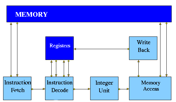
Figure 1 shows a typical implementation of a simple pipelined MIPS
architecture. The Integer Unit is used for both data and address
arithmetic, so load/store instructions are processed by the Integer
Unit before being sent to the Memory Access Unit and thence to
Memory. The Integer Unit also executes the additions required for
integer test and relative branch instructions, so the Memory Access
Unit also executes branches.
The Integer Unit receives its operands from the Instruction Decode
Unit, which is closely coupled to the Registers. These consist of 32
Integer Registers. The results from both arithmetic/logic and load
instructions are returned to the Registers by the Write Back Unit.

Figure 1. Typical Simple MIPS Pipeline
HASE MIPS Simulation Model
The HASE simulation of the simple pipeline version of the MIPS
processor is one of a number of HASE MIPS/DLX simulations, each of
which attempts to model one of the ways in which a MIPS or DLX
architecture might be implemented in hardware. The MIPS models contain
entities representing each of the components in the MIPS architecture,
the memory, the registers and the pipeline units, together with three
other entities which aid visualisation of the activities in the
system: the Clock, the Data Hazard and Pipeline displays. In all, six
types of file are required to construct the model:
- HASE definition files (EDL and ELF)
- Entity behavioural definition files
- Ancillary entity files (the Clock, etc)
- Global function files
- Icon files (held in a sub-directory)
- Memory and register content files

Figure 2. The HASE MIPS Model
The Clock entity sends (untraced) clock signal packets to the
other units and each Unit sends a DONE signal back to clock when it
has completed its actions. Each clock signal is generated when all
units are done, thus ensuring that the architecture acts as a
synchronous system. There are two signals in each clock period
(corresponding to rising and falling edges of a squarewave in hardare)
denoting the start of phases 0 and 1 of the period. Entities compute
in phase 0 and communicate in phase 1. During animation the Clock icon
displays the current phase of the clock (P0 or P1) and the value of a
clock cycle counter. The simulation ends when the Clock Counter value
reaches a parameter value set in the Parameters box or when a BREAK
instruction is executed.
Simple MIPS Model - Instruction Set
The HASE simulation model of the MIPS with a simple pipeline implements
the subset of the MIPS I instruction set shown in Tables 1a - 1f.
Branch and Jump Instructions
To simplify programming of the simulation model, jump and branch
instructions can use either integer addresses/offsets or labels (as
they would in assembly code). Labels can be added anywhere in the
program; they should occupy their own line and end with a colon (:).
The Demonstration page shows an example of how labels can be used.
The PC and PPC each have two fields: a label and an offset. At the
start of the simulation, the Memory entity creates a table of labels
and their absolute addresses. When fetching instructions, the Memory
entity adds the offset to the label to get the absolute address of the
instruction.
For a branch instruction, the use of a label differs from the use of
an offset value. When an integer offset is used, the offset value in
the instruction is added to the current value of the PC offset field.
When a label is used, the label in the instruction is copied into the
PC label field and the offset field is set to 0.
Similarly, when a jump instruction uses an integer value, the offset
field in PC is set equal to this value and the label field is set to
'main'. When a jump instruction uses a label, the label in the
instruction is copied into the PC label field and the offset field is
set to 0.
The initial value of the label in the PPC and PC is 'main';
this is the starting address of the program (instruction memory
address 0).
Note: Despite labels occupying their own line they do not count as
instructions and therefore take up no instruction memory. This is an
important consideration when using an (absolute) jump or (relative)
branch, as line numbers will not reflect instruction addresses.
Therefore it is advisable not to use a mixture of labels and offset
values in one program.
| Instruction | Description | Example | Result |
| LB | Load Byte | LB R3 1(R0) |
Loads Byte from memory location 1 |
| LBU | Load Byte Unsigned | LBU R4 1(R0) |
Loads Byte Unsigned from memory location 1 |
| SB | Store Byte | SB R1 1(R0) |
Stores Byte in R1 into memory location 1 |
| LH | Load Halfword | LH R4 2(R0) |
Loads Halfword from memory location 2 into R4 |
| LHU | Load Halfword Unsigned | LHU R4 2(R0) |
Loads Halfword Unsigned from memory location 2 into R4 |
| LUI | Load Upper Immediate | LUI R1 124 |
Load 124 in the the upper half of regester R1 |
| SH | Store Halfword | SH R5 6(R0) |
Stores Halfword from R5 into memory loction 6 |
| LW | Load Word | LW R4 8(R0) |
Loads Word from data memory location word 8 into R4 |
| SW | Store Word | SW R3 16(R0) |
Stores Word in R3 into location 16 in data memory |
Table 1a. Load/Store Instructions
| Instruction | Description | Example | Result |
| ADDI | Add Immediate Word | ADDI R1 R2 -4 |
Store R2 + -4 in R1 |
| ADDIU | Add Immediate Unsigned Word | ADDIU R1 R2 16 |
Store R2 + 16 in R1 |
| ADD | Add Word | ADD R1 R2 R3 |
Store R2 + R3 in R1 |
| ADDU | Add Word Unsigned | ADD R1 R2 R3 |
Store R2 + R3 in R1 |
| SUB | Subtract Word | SUB R1 R2 R3 |
Store R2 - R3 in R1 |
| SUBU | Subtract Word Unsigned | SUB R1 R2 R3 |
Store R2 - R3 in R1 |
| SLT | Set on less than | SLT R1 R2 R3 |
If R2 is less than R3 set R1 to be 1 else set it to 0 |
| SLTI | Set on less than Immediate | SLTI R1 R2 5 |
If R2 is less than 5 then set R1 to 1 else set it to 0 |
| SLTU | Set on less than Unsigned | SLTU R1 R2 R3 |
If the unsigned value of R2 is less than the unsigned
value R3 set R1 to 1 else set it to 0 |
| SLTIU | Set on less than Immediate Unsigned | SLTIU R1 R2 6 |
If the R2 is less than 6 (after sign extension)
set R1 to 1 else set it to 0 |
Table 1b. Arithmetic Instructions:
| Instruction | Description | Example | Result |
| AND | And | AND R1 R2 R3 |
Stores result of R2 AND R3 into R1 |
| ANDI | And Immediate | ANDI R1 R1 19 |
Stores the result of R1 AND 19 back into R1 |
| OR | Or | OR R1 R2 R3 |
Stores result of R2 OR R3 into R1 |
| ORI | Or Immediate | ORI R1 R1 128 |
Stores the result of R1 OR 128 back into R1 |
| XOR | Exclusive Or | XOR R1 R2 R3 |
Stores result of R2 XOR R3 into R1 |
| XORI | Exclusive Or Immediate | XORI R1 R1 64 |
Stores the result of R1 OR 64 back into R1 |
| NOR | Nor | NOR R1 R2 R3 |
Stores result of R2 NOR R3 into R1 |
| SSL | Shift Word Left Logical | SSL R1 R2 4 |
Shift R2 4 bits to the left and store in R1 |
| SRL | Shift Word Right Logical | SRL R1 R2 2 |
Shift R2 2 bits to the right and store in R1 |
| SRA | Shift Word Right Arithmetic | SRA R3 R4 2 |
Arithmrticaly shift R4 2 bits right and store in R3 |
| SLLV | Shift Word Left Logical Varable | SLLV R1 R2 R3 |
Shift R2 left by R3 bits and store in R1 |
| SRLV | Shift Word Right Logical Varable | SRLV R1 R2 R3 |
Shift R2 right by R3 bits and store in R1 |
| SRAV | Shift Word Right Arithmetic Varable | SRAV R1 R2 R3 |
Shift R2 right arithemeticaly by R3 bits and store in R1 |
Table 1c. Logical Instructions:
| Instruction | Description | Example | Result |
| J | Jump | J 8 |
Jump to instruction 8 |
| JR | Jump Register | J R1 |
Jump to the instruction number held in R1 |
Table 1d. Jump Instructions:
| Instruction | Description | Example | Result |
| BEQ | Branch on equal | BEQ R1 R2 4 |
Branch forward 4 instructions if
R1 and R2 are equal |
| BNE | Branch on not equal | BNE R1 R2 8 |
Branch forward 8 instructions if
R1 and R2 are not equal |
| BLEZ | Branch on less than or equal to zero | BLEZ R2 -2 |
Branch back 2 instructions if
R2 is less than or equal to zero |
| BGTZ | Branch on greater than zero | BGTZ R2 -2 |
Branch back 2 instructions if
R2 is greater than zero |
| BLTZ | Branch on less than zero | BLTZ R2 3 |
Branch forward 3 instructions if
R2 is less than zero |
| BGEZ | Branch on greater than or equal to zero | BGTZ R2 5 |
Branch forward 5 instructions if
R2 is greater than or equal to zero |
| BLTZAL | Branch on less than zero and link | BLTZAL R2 3 |
Branch forward 3 instructions if
R2 is less than zero |
| BGEZAL | Branch on greater than or equal to zero and link | BGTZAL R2 5 |
Branch forward 5 instructions if
R2 is greater than or equal to zero and link |
Table 1e. Branch Instructions:
| Instruction | Description | Example | Result |
| BREAK | Breakpoint | BREAK |
Halt |
| NOP | No Operation | NOP |
No operation |
Table 1f. Other Instructions:
The Pipeline Units
Instruction Fetch
The Instruction Fetch Unit accesses the Memory for instructions using
the address in a Prefetch Program Counter (PPC). PPC is initially set
equal to 0 (as is the PC register in the Memory Access Unit). If the
IF Unit decodes a branch, it enters Held mode, waiting for the branch
to be executed by the Memory Access Unit. If the branch results in a
change to PC (i.e. other than by a normal increment) the
prefetched instruction waiting to be copied into the Input Buffer has
to be discarded. Because of the prefetching, there has to be at least
one extra instruction (e.g. NOP 0) at the end of a program.
Instruction Decode
The Instruction Decode Unit receives instruction packets from the
Instruction Fetch Unit and sends instruction/operand packets to the
Integer Unit. Before accessing operands from the Registers, it checks
for data hazards (q.v.). If a hazard is detected, the Unit
enters the Held state and the instruction remains in the Instruction
Decode Unit until the next clock, when the checks are repeated.
Integer Unit
The Integer Unit receive instruction/operand packets from the
Instruction Decode Unit and sends instruction/operand packets to the
Memory Access Unit. In the current model the result of the
arithmetic/logic instruction is computed using native-mode operations
of the simulation execution platform. Detailed register transfer
level simulation models of the arithmetic units may be developed in
the future.
Memory Access
The Memory Access Unit receives instruction packets from the Integer
unit. Each packet contains two data fields in addition to the
instruction and status fields. Arithmetic instruction packets contain
the data to be sent to the registers via the Write Back Unit in the
data1 field. Load instruction packets contain a memory address in the
data1 field which is sent to the Memory Unit. The data returned from
the Memory is passed to the Write Back Unit. Store instruction
packets contain a memory address in the data1 field and the data to be
sent to Memory in the data2 field. Branch instruction packets contain
the new PC address or the offset in the instruction field of the
packet. Conditions are evaluated in the relevant Execution Unit and
carried through as bits in the Status field of the packet. When the
appropriate change has been made to the Program Counter, an untraced
packet is sent to the Instruction Fetch Unit to unlock the Held
condition in that Unit and to update the Prefetch Program Counter.
Write Back
The Write Back Unit receives packets from the Memory Access Unit.
Whenever a valid packet is received, the Write Back Unit constructs a
Register Write Request packet and sends it to the Registers.
The Registers have three ports, two for reading and one for writing.
The Registers unit is not clocked and acts immediately on each packet
it receives. To ensure that the simulation works correctly, there is
a short delay in the Instruction Decode unit before it performs the
WAW/RAW checks or reads the register values, i.e. a value
being written in one clock cycle can also be read in that clock
cycle.
Memory and Registers
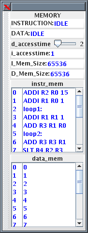
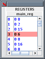
The contents of the memory and the registers are displayed in the HASE
Project Inspector Panel via the Parameters tab. Sections of the
Parameters display can be detached by clicking on the hashed area at
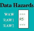
the left of the section. The Figure 3 shows examples of the detached
memory and registers windows. Also shown is the Data Hazards display
as seen in the Project pane when there is RAW hazard on register R5.
Figure 3. Memory, Registers and Data Hazards Displays
The Memory
The Memory contains two arrays, one for instructions and one for data.
These are held separately because instructions are held in readable
(string) form for visualisation purposes whilst data values are held
as integers. Each word in both memories contain its own byte address
as well as its instruction or data. When a project is loaded, HASE
looks for files with the same name as each of the arrays declared in
the .edl file, but with a .mem extension and loads the contents into
the corresponding array, e.g. the contents of
MEMORY.instr_mem.mem are loaded into the instruction memory. The
default MEMORY.instr_mem.mem supplied with the project files contains
a short demonstration program. Replacememt programs, which are copied
into this file before a simulation us run, must contain the byte
address as well as an instruction on each line.
The Memory receives instruction requests from the Instruction Fetch
Unit and Read/Write requests from the Memory Access Unit and, as
appropriate, either returns the contents of the requested memory word
to the requesting unit or updates it. It checks for invalid
addresses, and sets an error flag in the Scoreboard if either occurs.
The size of each array is determined by parameter of the Memory
entity, set to 256 as a default.
The Registers
The Registers are defined in a similar way to the Memory. Each word in
the Main Registers array contains an index number field, a data field
and a 'Busy Bit' field. All the data and Busy Bit values are initially
set to zero. Main Register 00 is read-only, i.e. writing to it
has no effect.
Data Hazards
Data Hazards occur when, for example, an instruction requires the
result of a previously issued but as yet uncompleted instruction.
Occurrences of these hazards are displayed by a separate Data
Hazards entity in the HASE model.
Data hazards are handled through Use bits. Each register has a
Use bit which is set when an instruction that will write to the
register is issued and reset when the result is written to the
register. In the HASE MIPS model the registers are implemented as C++
structs with two fields: Use bit and value. In the Register Display
Window shown in Figure 3, for example, Register 5 has its Use bit set
and has a value of 16, while all the others are in the reset
state. Before accessing a source or destination register, the
Instruction Decode Unit invokes a class in the Registers entity which
reads the relevant Use bit. If the Use bit for a Register required as
a source operand is set, then there is a RAW hazard, as shown for
Register 5 in the Data Hazards Display window. If the Use bit for a
Register required as a destination operand is set, then there is a WAW
hazard.
The Pipeline Display
The animation facilities of HASE allow the user to observe the state
of each pipeline entity (Void, Active, Held) and the contents of the
memory and registers, and to see instruction/data packets moving
between entities. Once these packets have arrived, however, the user
can no longer see which instruction is in which unit. Displaying an
instruction within or close to the corresponding icon would be
possible (c.f. the PC and PPC values) but would clutter the
display. A separate Pipeline Display entity is therefore used to
allow the user to follow the progress of instructions through the
pipeline.
At the start of Clock phase 0 each pipeline entity sends an (untraced)
packet to the Pipeline Display entity containing a copy of the
instruction and status fields from within its own input packet. If the
instruction is valid, the Pipeline Display entity 'prints' the
instruction to the appropriate place on the screen; if the instruction
is not valid it prints 'VOID'.
Demonstration Program
When first loaded, the model contains a program in its Instruction
Memory which finds all prime numbers between 0 and 15. The Data
Memory is initilised with the numbers 0 to 15. The program has two
nested loops. The inner loop sets values in memory which are multiples
of n (held in R1) to zero; n (initially set to 1) is incremented at
the start of each iteration of the outer loop. The program ends when
n reaches the limit of 15 set in R2. The non-zero numbers remaining in
memory are prime numbers. The program runs for 615 clock cycles.
| Instruction | Result/Comment |
| ADDI R2 R0 15 | R2 = R0 + 15 (=15) |
| ADDI R1 R0 1 | R1 = R0 + 1 (=1) |
| loop1: | Label - does not count as an instruction |
| ADDI R1 R1 1 | R1 = R1 + 1 (increment R1 by 1) |
| ADD R3 R1 R0 | R3 = R1 + R0 (copy R1 to R3) |
| loop2: | Label - does not count as an instruction |
| ADD R3 R3 R1 | R3 = R3 + R1 (increment R3 by R1) |
| SLT R4 R2 R3 | R4 = 1 if R2 < R3 else R4 = 0 |
| BNE R4 R0 done | Branch to done if R4 != R0 (R4 != 0) |
| SLL R5 R3 2 | R5 = R3 Left shifted 2 places |
| J loop2 | Branch to loop2 |
| SW R0 0(R5) | Delay slot: Store R0 at memory location R5 |
| done: | Label - does not count as an instruction |
| BNE R1 R2 loop1 | Branch to loop1 if R1 != R2 |
| NOP | Delay slot: No operation |
| BREAK | End the simulation |
| NOP | No operation |
Return to Computer Architecture Simulation Models

HASE Project
Institute for Computing Systems Architecture, School of Informatics,
University of Edinburgh
Last change 15/02/2023


