
Predication is a technique which aims to reduce pipeline stalls due to control hazards. It allows branches to be removed from the code by executing both the if and else parts of a branch in parallel, removing the problem of mispredicted branches. In the Intel IA-64 for example, an instruction can have a predicate tag appended to it by the compiler and the instruction is only allowed to write its result if the corresponding predicate is true.
This website explains how predication works in the IA64 and describes a HASE simulation model of the DLX architecture, modified to include predication so as to illustrate the way predication work.
The files for this model can be downloaded as a zip file from dlx-pred_v4.3.zip
Instructions on how to use HASE models can be found at Downloading, Installing and Using HASE.
The Intel IA-64 is an example of a commercial microprocessor that uses predication. Most instructions in the IA-64 (excluding some such as `return from exception') can have a predicate tag appended to them by the compiler. The instruction will only be allowed to write its result if the corresponding predicate is true. A branch construct can be rewritten using predication by making the if part predicated on a certain predicate register and the else part predicated on a complimentary register. Since only one of the pair of predicate registers holds true, only one of the paths through the branch will write its result.
Comparison instructions, similar to those used to set conditions for a traditional conditional branch, are used to perform a comparison operation and set a pair of registers, one to true and one to false, depending on the result of the comparison.
Predication relies on the parallel execution of both instruction paths and thus requires the architecture to feature multiple instruction issue. Since the IA-64 can issue several instructions per cycle, it can, for example, issue a compare and two instructions predicated on that instruction in the same cycle. By the time the predicate is needed, it is already available after the comparison has been done. This is already a one cycle improvement over a system without predication, even if that system correctly predicts the branch.
Predication can be illustrated by the example given in [1] which uses the following code segment:
if a[i].ptr != 0 {
b[i] = a[i].l;
} else {
b[i] = a[i].r;
}
i = i + 1;
The value of a[i].ptr is loaded from memory and used as the condition for a conditional branch. In a traditional architecture this code is scheduled as four basic blocks (as shown at the left in Figure 1); the compare, the if part, the else part, and the add instruction which follows the conditional statement. Clearly, the result of the compare is difficult to predict. Even if a prediction scheme is used, it cannot correctly predict every time, and the penalty for an incorrect prediction is a pipeline stall costing several clock cycles.
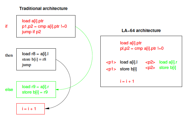
Figure 1. Traditional v. Predication Model of Code Execution
After the load instruction, a new compare instruction, cmp, compares the loaded value with zero, and sets the pair of predicate registers. The true predicate p1, is set if the compare was true, and the false predicate p2, is set if the compare was false. Only the path with the true predicate is allowed write its result to memory, the other instruction being ignored.
The instruction word (Figure 2) is 70 bits long (but fetched as two successive 35 bit words in the model). Each half consists of a DLX instruction together with an additional 3-bit field to specify which of the predicate registers the instruction is predicated on. ps1 and ps2 are the source predicate registers. If an instruction is not conditional, its source predicate register is set to P1, which is always true (P0 is always 0).
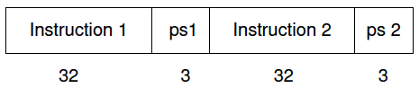
Figure 2. DLX-PRED Instruction Word
New versions of the DLX compare instructions are required to operate on the predicate instructions. The standard DLX architecture has six comparison instructions which compare the values in two registers and set the result in a third within the set of general purpose registers. The conditions available are: equality (SEQ), not equal (SNE), greater than (SGT), greater than or equal (SGE), less than (SLT) and less than or equal (SLE). Corresponding instructions also exist for comparison of one register with an immediate value.
The DLX-Pred instruction set includes a second set of comparison instructions which set a pair of specified predicate registers, one to true and one to false, depending on the result of the comparison. These instructions are named similarly to the DLX compare instructions, but with the addition of a P, to show that they set predicate registers rather than general purpose registers. Thus, the instructions are SPEQ, SPNE, SPGT, SPGE, SPLT and SPLE.
The instruction format is shown in Figure 3. The field marked op stands for any of the six possible op-codes.
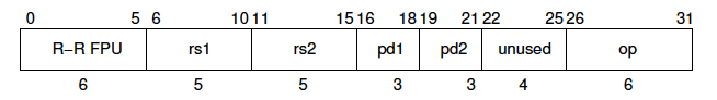
Figure 3. DLX-PRED Compare Instruction Format
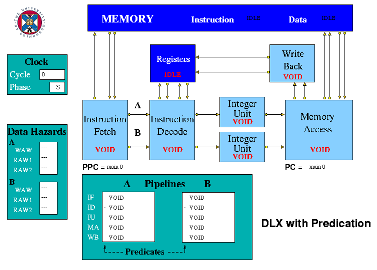
Figure 4. The HASE DLX-Pred Model
In the model there is a mechanism for resetting the busy bit of a register which was set busy by an instruction which does not have its predicate set.
The Instruction Decode unit sends an instruction to each of the two Integer Execution units.
The Memory Access unit receives results from both Execution units. It accesses the predicate registers and determines whether or not each instruction is to complete. If the predicate for an instruction is true, the instruction may proceed as normal. However, if the predicate is false, the instruction is terminated, does not read or write memory and does not proceed to the Write Back unit if it otherwise would.
The predicate registers are contained in the Memory Access unit which is the only unit which ever requires access to them. It is in Memory Access that they are read to determine whether an instruction should proceed through the unit. It is also in the Memory Access unit that the result of the compare arrives so it is simple to write the result into predicate registers in that unit. Keeping predicate registers in Memory Access, rather than with the general purpose registers, eliminates the need for any forwarding of predicates and hazard detection.
The DLX-Pred Pipeline display includes a field for each instruction in the Memory Access unit showing its predicate value, thus indicating whether or not that instruction will be executed.
if a[i].ptr != 0
{b[i] = a[i].l;}
else
{b[i] = a[i].r;}
i = i + 1;
The DLX-Pred code for this segment is contained within a loop which is repeated 8 times using a decrementing loop counter. This code is shown in Figure 5 along with the registers assignments in Figure 6. In the model the code can be seen in the memory via the Parameters tab of the Project Inspector. The data_mem section contains eight triplets of data, the pointer (0 = left, 1 = right) and the left and right hand values. As the program runs, the selected data values of the a array, left or right according to the pointer, are copied to successive locations in the b array.
|
|