

In directory based systems, the directory can be held centrally with the main memory in a multi-processor system or can be distributed among the caches as singly or doubly linked lists. This website contains models demonstrating each of these three mechanisms. For each model, students can be asked, as an exercise, to write a report explaining what protocol actions occur for each of the read and write requests that the processors make to their caches, e.g. by listing the packets which are sent around the system in response to each request and explaining the purpose of each packet.
The files for the Central Directory protocol model can be downloaded from dircache_v1.3.zip
The files for the Singly-linked list protocol model, based on the coherence mechanisms used in the SDD (Stanford Distributed Directory) protocol, can be downloaded from dircache_v2.2.zip
The files for the Doubly-linked list protocol model, based on the coherence mechanisms used in the SCI (Scalable Coherent Interface) protocol, can be downloaded from dircache_v3.5.zip
Instructions on how to use HASE models can be found at Downloading, Installing and Using HASE.
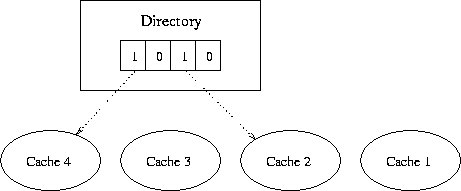
Figure 1. Central directory structure
Write Update Policy: When a cache receives a write request from its processor, then if it finds a Write Hit, it sends a write update packet to the memory. The memory updates the block, sends out any necessary update packets to other caches and returns a write acknowledgement packet to the originating cache. If the line is empty and the cache finds a Cache Miss, its sends a write request to the memory. The memory updates the block, sends out any necessary update packets to other caches and sends the (updated) block to the originating cache as part of a write acknowledgement. When a cache receives an update packet, it writes the new data into the line containing the address in the packet.
Replacements: If a Read or Write Miss is on a line containing a different valid address from the one requested, the cache sends an invalidate request for that address to memory. The memory sets the corresponding bit in the directory vector for that line to 0 and sends an invalidate acknowledgement packet to the cache. When the cache receives the acknowledgement packet, it issues a read or write request as for a Read or Write Miss on an empty line.
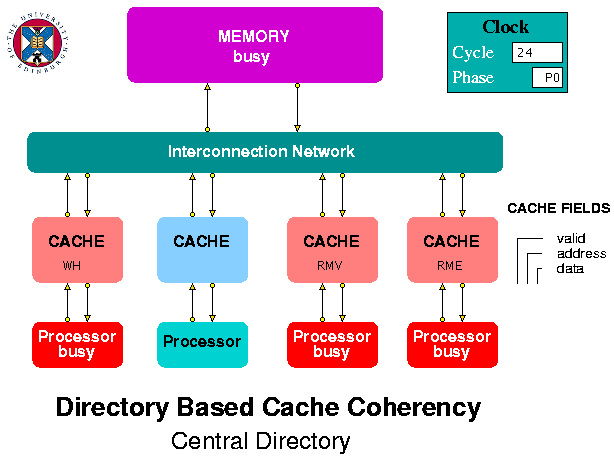
Figure 2. Central Directory Simulation Model
| R | 0 | 0 |
| R | 6 | 0 |
| W | 6 | 42 |
| W | 14 | 53 |
| Z | 0 | 0 |
The caches are the most complex entities in the model. They receive request packets from the processors and request and response packets from the interconnection network. Each packet contains a request type field. Packets from the processors have a single letter type field corresponding to a read request (r or R) or a write request (w or W). A cache displays its response to an incoming request as RH (Read Hit), RME (Read Miss on an Empty line), RMV (Read Miss on a Valid line containing a different address), WH (Write Hit), WME (Write Miss on an Empty line), WMV (Write Miss on a Valid line containing a different address).
A packet passing between caches or between the caches the memory, via the interconnection network, can have one of the following types:
The processor array files included in the model contain a series of Read and Write requests which demonstrate several of the protocol actions. Users of the model are invited to observe the simulation play-back to see their effects. These are different according to the choice of write-invalidate or write-update inter-cache policy. The choice of policy is made via a global parameter (at the bottom of the parameters window). Parameters can only be changed before the start of a play-back (i.e. normally after a re-wind) and the simulation needs to be re-run once a change has been made.
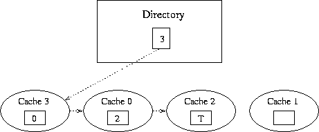
Figure 3. Singly Linked List Structure
When a second cache receives a request for an address in this block, it directs a read request to memory. The memory responds by returning a pointer to the head of the list, in this case cache 0. The memory also updates the directory for the block, to indicate that cache 0 is now the head of the chain. When cache 0 receives this pointer, it sets its successor field to point to the old head of the list, effectively prepending itself to the list. In Figure 3, cache 3 was the next to request this address, so it is the head and points to cache 0.
Write Requests: A processor can only write data if it has the only copy of the block in question. However, it cannot know this, so if it has a copy, and therefore gets a Write Hit, it must write through to memory. The packet it sends to memory includes a copy of its successor field. The memory checks to see if the successor field is -1 and if the number of the cache matches the pointer in its directory. If so, the memory updates its data and directory entry for the block and sends a Write Acknowledge to the cache. If the requesting cache is not both the head and tail of the list, the memory sends an Invalidate packet to the head of the list. This packet includes the identity of the requesting cache (the new head of the list). A cache receiving an Invalidate packet invalidates its entry for that address and, if it is not the tail of the list, sends an Invalidate to the next cache in the list. The cache that is the tail of the list sends an Invalidate Acknowledge to the original requesting cache which now completes its write operation.
Replacements: Sometimes a cache needs to remove itself from a list because it gets a collision miss. In this case, the whole list must be invalidated because the cache does not know where it is in the list (unlike the situation in a doubly linked list protocol describe below). It therefore sends an Invalidate packet to the memory. If the cache is the head of the list, the memory replies with an Invalidate Acknowledge; if it is not the memory sends an Invalidate packet to the head of the list. As for a Write Request, the initiating cache will eventually receive an Invalidate Acknowledge, after which it can send a Write Request to the memory.
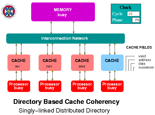
Figure 4. Singly Linked List Model
| R | 0 | 0 |
| R | 6 | 0 |
| W | 6 | 42 |
| W | 14 | 53 |
| Z | 0 | 0 |
The caches are the most complex entities in the model. They receive request packets from the processors and request and response packets from the interconnection network. Each packet contains a request type field. Packets from the processors have a single letter type field corresponding to a read request (r or R) or a write request (w or W). A cache displays its response to an incoming request as RH (Read Hit), RME (Read Miss on an Empty line), RMV (Read Miss on a Valid line containing a different address), WH (Write Hit), WME (Write Miss on an Empty line), WMV (Write Miss on a Valid line containing a different address).
A packet passing between caches or between the caches the memory, via the interconnection network, can have one of the following types:
The processor array files included in the model contain a series of Read and Write requests which demonstrate several of the protocol actions. Users of the model are invited to observe the simulation play-back to see their effects.
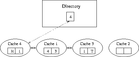
Figure 5. Doubly Linked List Structure
When a second cache receives a request for an address in this block, it directs a read request to memory. The memory responds by returning a pointer to the head of the list, in this case cache 3. The memory also updates the directory for the block, to indicate that cache 1 is now head of the chain. When cache 1 receives this pointer, it sends a prepend request to the previous head. On receiving this request, cache 3 sets its predecssor pointer to cache 1 and returns the data to cache 1. Cache 1 then sets its predecessor pointer to be the head of the list, and its successor pointer to cache 3. In Figure 5, this process has been repeated as a result of a request from Cache 4, so that the directory entry in Memory points to Cache 4. Cache 4's predecessor pointer is head pointer and its successor pointer to cache 1. In Cache 1, the predecessor pointer points to Cache 4 and the successor pointer to cache 3. In Cache 3, the predecessor pointer points to Cache 1 and the successor pointer is the tail marker.
Write Requests: A processor can only write data if it has the only copy of the block in question: it must be the only processor in the chain with its predecessor pointer pointing to memory and its successor pointer indicating that it is tail. In order to obtain such exclusive access, the chain head must first become the head of the list (even if it is already part of it), then write its data and then purge the other caches from the list. It does this by sending a purge signal to the next processor in the chain. When a processor receives a purge, it replies with an acknowledgement message, containing a pointer to the next cache in the list. This successor pointer is used to purge the next sharing list entry. When the writing cache receives an acknowledgement from the tail of the chain, it knows it is the only cache left.
Replacements: Sometimes a cache needs to remove itself from the list by performing a roll out. For example, it might need to replace one of its cache blocks with a different memory block. In this case, before accessing memory for the new block, it sends a command containing its successor pointer to its predecessor, telling that cache to update its successor pointer, and a command containing its predecessor pointer to its successor, telling that cache to update its predecessor pointer. A roll out must also be performed if the cache is part of a list, but not the head of it, when it responds to a write request from its processor.
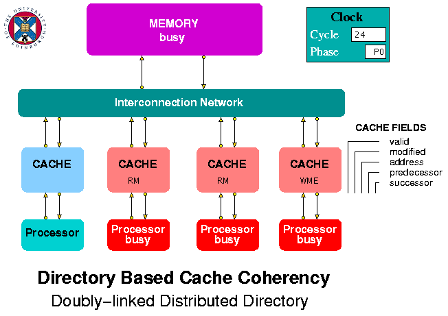
Figure 6. Doubly Linked List Model
| R | 4 |
| R | 5 |
| W | 6 |
| Z | 0 |
The interconnection network simply routes packets from its inputs, at a rate of one per clock period, to the output address that forms part of each packet. The memory is modelled simply as an array containing integer values, initially all zero, that point to whichever cache is head of the list for the corresponding memory block (the blocks themselves are not modelled).
The caches are the most complex entities in the model. They receive request packets from the processors and request and response packets from the interconnection network. Each packet contains a request type field. Packets from the processors have a single letter type field corresponding to a read request (r or R) or a write request (w or W). A cache displays its response to an incoming request as RH (Read Hit), RM (Read Miss), WHH (Write Hit and Head of list), WHN (Write Hit but Not head of list), WME (Write Miss on an empty line), WMN (Write Miss on a Non-empty line).
A packet passing between caches or between the caches the memory, via the interconnection network, can have one of the following types:
The processor array files included in the model contain a series of Read and Write requests which demonstrate several of the protocol actions. Users of the model are invited to observe the simulation play-back to see their effects.
Return to Computer Architecture Simulation Models
